〔
Measuring Method
〕
For the safety operation keep and pay attention to the cautions and warnings stated in
this manual.
▲
DC Current (DCA ) Measurement
1) Set the range switch
③
from OFF to 40A or 400A
2) Set AC/DC switch
④
to DC
3) At the time of DC current measurement make “0”
adjustment by ADJ switch before measurement.
4) Open clamp jaw and clamp CT to the conductor to
be measured and close CT completely (Set the
conductor to be located in the center position
of CT).
5) Read the displayed value. (In case of over range, the
display will show “OL”).
6) In the place where can hardly read the display, use
The Data Hold
⑤
.
7) After the measurement, set the range switch
⑧
to OFF.
▲
AC Current (ACA
~
) Measurement
1) Set the range switch
③
from OFF to 40A or 400A
2) Set AC/DC switch
④
to AC
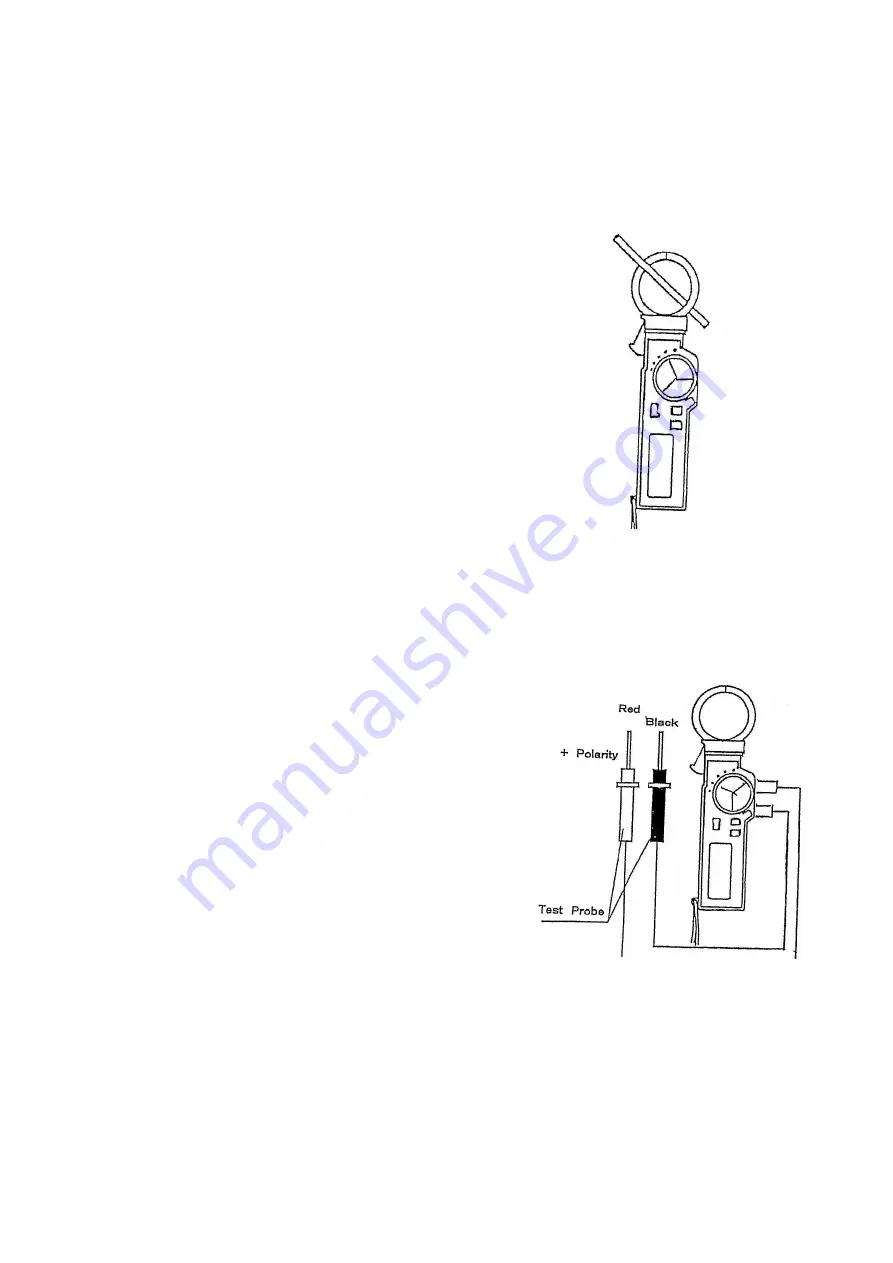
3) Open clamp jaw and clamp CT to the conductor to be measured and close CT
completely (Set the conductor to be located in the center position of CT).
4) Read the displayed value. (In case of over range, the display will show “OL”).
5) In the place where can hardly read the display, use the Data Hold Switch
⑤
.
6) After the measurement, set the range switch to OFF.
▲
DC Voltage ( V) Measurement
1) Set the range switch
③
to V.
2) Set AC/DC switch
④
to DC
3) Insert test probe to the input terminal.
4) Apply the test probe to the part to be measured.
5) Read the displayed value.
6) After the measurement, set the range switch to OFF.
▲
AC Voltage (
~
V) Measurement
1) Set the range switch
③
to V.
2) Set AC/DC switch
④
to AC
3) Insert test probe to the input terminal.
4) Apply the test probe to the part to be measured.
5) Read the displayed value.
6) After the measurement, set the range switch to OFF.
▲
Resistance (
Ω
) Measurement
1) Set the range switch
③
to
Ω
.
2) Apply the test probe to the part to be measured.
3) Read the displayed value.
4) After the measurement, set the range switch to OFF.


