background image

IHL_UDARA_2016_11_04_BEGB

 15 

4.2.4 

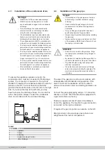
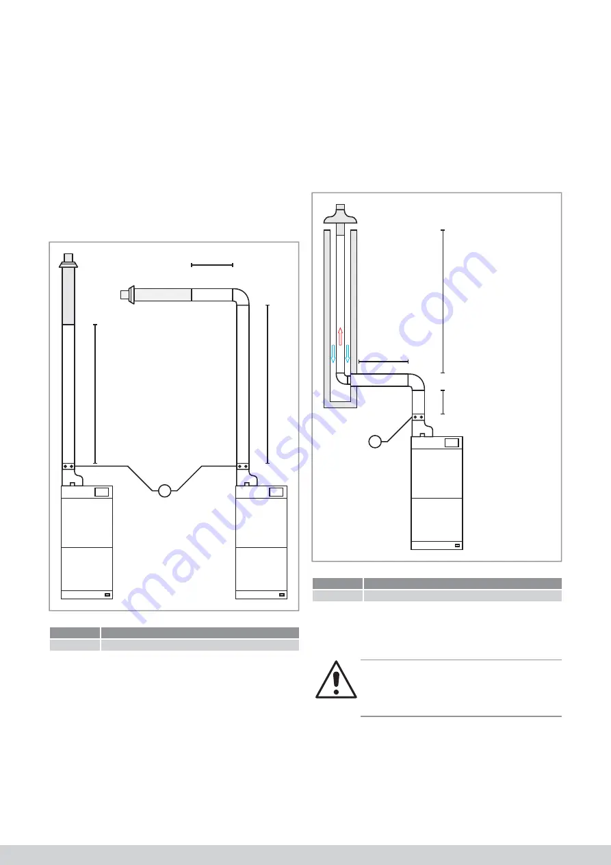
Concentric systems (C12/C32)

The 

fl

 ue gas outlet (FGO) pipe is surrounded by the 

combustion air supply (CAS) pipe with regard to a 
concentric 

fl

 ue gas outlet system. Multicalor carries a 

full range of concentric pipes. 

The Y-pipe supplied with the 

fl

 ue gas outlet terminal 

must be positioned on top of the appliance with regard 
to a concentric connection. 

Always position a measuring point in the concentric 
piping, by preference, immediately after the Y-pipe or, 
if this is not possible, as close as possible to the 
appliance. 

L

L1

L2

1

Legend

Number

Meaning

1

Measuring point 

The length of the 

fl

 ue gas outlet plus the equivalent 

length of the bends must not exceed the maximum 
value speci

fi

 ed in item 4.2.7. 

4.2.5 

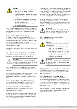
Chimney renovation (C92) 

It is sometimes interesting to install a special 

fl

 exible 

fl

 ue gas outlet pipe with a diameter of 80 mm in an 

existing 

fl

 ue gas outlet (conventional) 

fi

 replace. The 

combustion air can then be supplied through the air 
cavity between the 

fl

 ue gas outlet pipe and the existing 

chimney or in the room itself. The connection between 
the 

fl

 exible pipe in the old 

fl

 ue gas duct and the    

appliance can then take place in parallel or  


concentrically.

L1

L3

L2

1

Legend

Number

Meaning

1

Measuring point 

The length of the 

fl

 ue gas outlet plus the equivalent 

length of the bends must not exceed the maximum 
value speci

fi

 ed in item 4.2.7. 

Warning!

Do not use the old fl ues as combustion air supply if 
they have been used in the past as the FGO for fuel 
oil appliances, coal or wood burners or fi replaces. 

If you want to use this system, the existing 

fi

 replace 

must at least measure 150 mm x 150 mm when using 
a discharge pipe with a diameter of 80 mm. 

Summary of Contents for 10

Page 1: ...r and keep this document in the immediate vicinity of the appliance This appliance may not be operated by children people with a diminished mental capacity physical impairments or lack of knowledge unless under supervision or after receiving training on how to use the appliance safely and as long as they are aware of the possible risks Children may not play with the appliance under any circumstanc...

Page 2: ...ulating the combustion 20 5 3 Converting the appliance to propane 21 6 Operating and setting 22 6 1 In general 22 6 2 Modulating thermostat RC21 22 6 3 Air conditioning 23 6 4 Heat pump 23 6 5 Operation in heating mode 23 6 6 Setting as ventilation 23 6 7 The control panel 23 6 8 Changing settings 24 6 9 Error codes 26 7 Maintenance 27 7 1 Maintenance by the user 27 7 2 Maintenance by the installe...

Page 3: ...ee 33 11 3 Damage that is not covered by the guarantee 33 11 4 The following are not covered by the guarantee 33 11 5 Repairs 33 11 6 Service sets 33 12 Multicalor RC21 14 34 12 1 Setting the language date and time 34 12 2 Mode 12 3 Summer ventilation 36 12 4 Program 36 12 5 Switching off periods max of 2 periods 37 13 EC Declaration of conformity 38 14 Declaration of conformity KB 2004 01 08 39 ...

Page 4: ...4 IHL_UDARA_2016_11_04_BEGB ...

Page 5: ...ufacturer of the appliance As a user you must closely follow the maintenance instructions Ask your installer to go through this section if you have any questions 1 3 1 Danger of fatal injury because of gas leaks With regard to gas smells in buildings extinguish all naked flames such as from smoking cookers etc Do not operate any doorbells switches plugs telephones entry panels or other devices Clo...

Page 6: ...bsolutely sure that the environment in which the appliance is being installed cannot lead to any dangers because of floating dust and or flammable or corrosive substances or fumes Some parts of the appliance can become very hot during and shortly after use Only carry out activities such as maintenance after the appliance has completely cooled down 1 3 7 Risk of corrosion damage Chemical products s...

Page 7: ...ated and unnecessary bending Do not suspend the burner and mixing box from the flexible corrugated gas tube during maintenance 1 3 11 Material damage after water ingress If the appliance or parts of it are exposed to water ingress the appliance must be put out of service immediately All safety components that are exposed to water must subsequently be replaced ...

Page 8: ...ate the fan compartment of the Udara air heater This will limit condensation on the outer housing of the appliance In addition the condensate trap must be installed outside the appliance using an extended hose set with regard to the upflow versions of the Udara The condensate hoses in the fan compartment must also be safeguarded from frost for example by installing thermal insulation and or a heat...

Page 9: ... 614 0 818 1 035 Thermal efficiency at full load 106 2 106 3 106 4 106 6 106 8 106 8 Thermal efficiency at partial load 109 0 109 0 109 0 109 0 109 0 109 0 NOx emissions 30 mg kWh CLASS 5 EN1020 EN1319 Gas category I3P Maximum load on the lower value PCI G31 37 mbar kW 10 2 15 1 20 1 30 1 40 2 50 2 Minimum load on the lower value PCI G31 37 mbar kW 1 7 2 4 3 2 4 8 6 3 8 0 Maximum power G31 37 mbar...

Page 10: ...2 Flue gas outlet 3 Control panel 4 Probe discharge air temperature NTC 2 NTC 5 5 Flue gas outlet coupling 6 Mixing box and venturi 7 Ionisation electrode 8 Ignition electrode 9 Flexible gas tube 10 Burner management control system 11 Flue gas fan 12 Gas valve 13 Intake temperature probe NTC 1 14 Condensate discharge trap 15 System fan 16 Air filter in downflow in filter cabinet ...

Page 11: ...Thermostat connection d Condensate drain throughput 1100 300 370 410 535 A 60 A 120 75 A 60 660 720 725 A 30 470 675x410 3 4 1 Dimensions Downflow 1100 120 75 A 60 400 720 725 A 470x410 B B 40 400 515 Legend Udara 10 15 20 30 40 50 A 400 500 600 700 B 340 440 540 540 70 a Gas throughput b Power supply cable connection c Thermostat connection d Condensate drain throughput ...

Page 12: ...tect the flue gas outlet with a non flamma ble sheath if it is being guided through walls or cavities made of flammable material Always respect the free space of 25 mm between this sheath and the discharge pipe Every Udara appliance must be equipped with an individual FGO CAS Shared discharge systems are not permitted The burner compartment of the Udara is part of the combustion circuit The applia...

Page 13: ...e approval in accordance with the Gas Appliance Directive If the discharge of combustion gases and the supply of combustion air takes place through the wall the especially designed and approved wall gland MUGRO WALL must be used Connecting to another wall gland is not permitted in relation to the approval in accordance with the Gas Appliance Directive The flue gas outlet must be installed with a m...

Page 14: ...easuring point in the CAS and FGO L1 L2 L3 1 Legend Number Meaning 1 Measuring point 4 2 3 Parallel systems C12 C32 You can use a parallel system to discharge the flue gases Multicalor carries a range of supply and discharge pipes made of high quality PP and stainless steel The drawing below shows a parallel system The length of the flue gas outlet plus the equivalent length of the bends must not ...

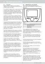
Page 15: ...ey renovation C92 It is sometimes interesting to install a special flexible flue gas outlet pipe with a diameter of 80 mm in an existing flue gas outlet conventional fireplace The combustion air can then be supplied through the air cavity between the flue gas outlet pipe and the existing chimney or in the room itself The connection between the flexible pipe in the old flue gas duct and the applian...

Page 16: ...utlet 30 30 30 30 30 20 C12 C32 80 125 mm Concentric systems with wall terminal Concentric systems with roof terminal 12 5 12 5 12 5 12 5 12 5 10 C12 C32 80 80 mm Parallell systems with wall terminal Parallell systems with roof terminal 20 20 20 20 20 15 C92 80 125 mm Concentric pipes dans la chaufferie Flexible pipes MG Flexline in the flue gas outlet 12 5 12 5 12 5 12 5 12 5 10 Bend 90 Bend 90 2...

Page 17: ...Do not discharge the condensate directly outside frost risk but discharge the water using the indoor drainage system If local standards require condensate neutra lisation you must install such a device before discharging the condensate down the drain The condensate drain MUST be installed with a slope 5 cm m towards the drainage system The trap must be installed outside the fan com partment and ho...

Page 18: ...oegang tot het ventilatorcompartiment belet een rooster of uitblaasplenum monteren op de uitblaasopening zodat er geen rechtstreekse toegang is tot het warmtewisselaarcomparti ment Dit rooster of plenum moet ook verhinde ren dat er brandbaar materiaal op de warmte wisselaar kan vallen Waarschuwing Alvorens u de Udara upflow gebruikt met terugname onderaan moet u de bodemplaat verwijderen langs hee...

Page 19: ...ing a long tool life filter from the range of accessories If you want to use an open return only possible if there are no appliances with an open combustion circuit in the set up room you can order a perforated readmis sion plenum f you are connecting an outdoor air duct a control valve must always be included in the outdoor air duct 4 5 4 Air distribution box dimensions Danger Internal acoustic o...

Page 20: ... replaced for example after a fault the calibration procedure must again be performed The simplest way in which to do this is through manual calibration using an RC21 thermostat Having a device with which you can also measure the NOx nitrogen oxide content in the flue gases is recommended to ensure the procedure is performed correctly Enter the installer password to start the procedure see the Tec...

Page 21: ...will also be tested on low power If you again confirm this test by pressing Confirm the new settings will be stored in the burner management control system The normal setting can be read from the table below Normal settings I2N Fase CS typ CS Max CS Min CO2 0 5 NOx 10 ppm CO 10 ppm Max 50 70 30 8 5 20 10 ppm Med 55 70 35 8 5 20 10 ppm Min 90 120 70 8 5 10 50 ppm Normal settings I3P Fase CS typ CS ...

Page 22: ...d and based on this the optimum power is determined to heat up the room quickly or to keep it comfortably warm The air quantity will be adjusted automatically to the discharge air temperature so that a pleasant indoor climate and an extremely uniform temperature is obtained The installer can set a low average or high air quantity These air quantities are linked to a low average or high air tempera...

Page 23: ...fan will always operate at the set low air speed even if there is no heat demand 6 6 3 Ventilation à vitesse moyenne De ventilator draait steeds op de ingestelde middelste luchtsnelheid ook indien er geen warmtevraag is 6 6 4 Ventilation à haute vitesse De ventilator draait steeds op de ingestelde hoge luchtsnelheid ook indien er geen warmtevraag is 6 7 Het bedieningspaneel Op het toestel is een b...

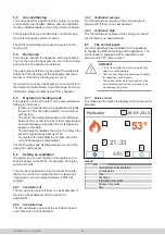
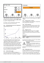
Page 24: ...s are discussed Since all screens are accessible through the same process not all screens will be discussed 6 8 1 Low average and high temperature You can set 3 air temperatures on the Udara a low average or high value To set these values press the air heater 2 menu button next system fan and then the first fan curve option on the setting menu 1 40 30 50 1 2 3 4 9 5 6 Next select the value that yo...

Page 25: ... is enke Installateurcodes Code Gebruikersniveau 123456 Power user 007007 Installateur Le code du niveau d utilisation technicien n est pas dévoilé qu àprès avoir suivi une information chez Multicalor Avertissement Modifier sans discernement des paramètres réser vés aux installateurs peut endommager l appareil ou faire en sorte qu il ne fonctionne plus convena blement Dans des circonstances normal...

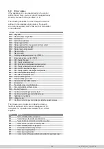
Page 26: ...o large E23 NTC 3 faulty optional discharge air temperature E40 NTC 1 fault intake temperature E10 NTC outdoor temperature fault E160 Problem with flue gas fan E53 Problem with flue gas outlet E83 No communication with thermostat E98 Internal error E71 Fan outside range in calibration mode E72 Poor combustion in calibration mode E162 Incorrect frequency E79 Control current of the gas valve too hig...

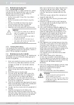
Page 27: ...report If the flue gases are hotter than 50 C check whether there is a problem with the system fan It is also possible that the load is too high 13 If the appliance does not start properly check the combustion Consult item 5 2 for more information if required If the combustion is correct but star ting problems occur anyway you must disassem ble the burner and check the distance between the ignitio...

Page 28: ...rk If a spark is not formed you must replace the high voltage cable the ignition electrode or the control unit 4 Check whether the protection shut off valve swit ches by measuring the voltage 5 Check whether gas is flowing in the protection shut off valve by measuring the drop in pressure over the valve during switching 6 Remove the burner and check the distance between the ignition electrode and ...

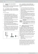
Page 29: ...e power supply 2 Check the connection of the control unit with the display 3 Check the fuses on the interface printed circuit board system fan display 4 Check the flat cable between the interface printed circuit board and the display Warning Pay attention to the correct connection of the flat cable If you press this incorrectly into the connec tor the display can be irreparably damaged 8 5 Flue ga...

Page 30: ...ventively because the flame is becoming unstable Also check the pressure in the gas pipe and also with other consumers switched on 8 11 Normal settings Udara HR DF 10 15 20 30 40 50 Starting speed flue gas fan min 1 4200 Maximum flue gas fan speed min 1 5900 6900 Minimum flue gas fan speed min 1 1500 Burner off at intake temperature then TSP 1 C 40 Maximum discharge air temperature overheat contro...

Page 31: ...GND TACHO NTC 5 STB GND HRG 134 COMBUSTION FAN N L UDARA SYSTEM BLOWER EV1 EV1 GAS VALVE MOD MOD NTC 2 SUPPLY 0V 12V TACHO PWM ENABLE GND NTC 1 RETURN GND NTC 4 OPTION GND NTC OAT OPTION GND NTC 3 OPTION Multicalor 28 03 2015 3 53 21 33 45 ECM 2 3 ECM 3 0 0 10V EBM 8 c v Tx Rx GND TACHO SPEED 15 16 10 3 X15 WHITE RED BLACK a b RC21 THERMOSTAT N PE L FUSE FACTORY INSTALLED FIELD INSTALLED MODEL UDA...

Page 32: ...D 15 BR UD 20 BR UD 30 BR UD 40 BR UD 50 Heat shield PCW 10 PCW 15 PCW 20 PCW 30 PCW 40 PCW 50 Condensate drain Upflow HF UD CAL UPFLOW Condensate drain Downflow HF UD CAL DOWNFLOW Air filter LFDF 13 28 LFDF 17 28 LFDF21 28 LFDF 25 28 10 2 Ordering procedure If you need to replace a part we recommend speci fying the related item code when ordering the relevant part as well as specifying the type o...

Page 33: ...ely dusty rooms without an intake filter in the CAS irreparable internal contamination of the heat exchanger when used in extremely dusty rooms without an intake filter in the CAS changes or adjustments to the appliance without the written approval of Multicalor Industries NV repairs performed with non original or incorrect material the heat exchanger when used in an atmosphere contaminated with c...

Page 34: ...g Yes 0 0 C General settings Esc Back Language Date and time Auto switch to DST Room sensor adjust Display FRA Yes 0 0 C General settings Esc Back Languge Date and time Auto switch to DST Room sensor adjust Display Eng Yes 0 0 C Date and time Cancel Confirm Date Time HOUR MINUTE 01 01 DAY MONTH YEAR 01 Jan 2015 Date and time Cancel Confirm Date Time HOUR MINUTE 14 01 DAY MONTH YEAR 22 Sep 2016 Gen...

Page 35: ... Menu Mode Room 22 4 C 25 0 C Room temperature Cancel Confirm 20 5 C Manual Thu 22 sep 2016 16 40 Menu Mode Room 22 4 C d on n on n 12 2 2 Setting the timer program Operation mode Cancel Confirm Heating Off Manual Operation mode Cancel Confirm Heating Off Manual Operation mode Cancel Confirm Heating Off Manual Operation mode Cancel Confirm Heating Off Automatic Thu 22 sep 2016 16 40 Menu Mode Room...

Page 36: ... 17 00 return 20 C 24 C 22 45 sleep 22 C 26 C Time scheduling Esc Back Monday Friday Day s 07 00 wake 22 C 24 C 09 00 leave 24 C 28 C 17 00 return 20 C 24 C 22 45 sleep 22 C 26 C Time scheduling Cancel Confirm Monday Friday Day s 07 00 wake 22 C 24 C 09 00 leave 18 C 28 C 17 00 return 18 C 24 C 22 45 sleep 22 C 26 C Time scheduling Cancel Confirm Monday Friday Day s 07 00 wake 22 C 24 C 09 00 leav...

Page 37: ...22 C 24 C 22 45 leave C C 22 45 return C C 22 45 sleep 22 C 26 C Time scheduling Cancel Confirm Saterday Sunday Day s 07 00 wake 22 C 24 C 22 45 leave C C 22 45 return C C 22 45 sleep 22 C 26 C Time scheduling Cancel Confirm Monday Friday Day s 07 00 wake 22 C 24 C 09 00 leave 18 C 28 C 17 00 return 18 C 24 C 22 45 sleep 22 C 26 C Time scheduling Cancel Confirm Saterday Sunday Day s 07 00 wake 22 ...

Page 38: ...chnigas Vilvoordsesteenweg 156 1120 Brussels Specifically applied harmonised standards EN 1020 Non household gas fired air heaters with forced convection for space heating with a net heat load of up to 300 kW and a fan for the transport of the combustion air and or gases EN 1196 Domestic and non domestic gas fired air heaters Supplementary requirements for condensing air heaters EN 1319 Domestic g...

Page 39: ...ing for all types Polluant CO mg kWh NOx mg kWh Mesure 15 30 The EC type investigation as determine in Annex II of the Royal Decree as well as safeguarding the conformity type as determined in Annex III are performed by Technigas Vilvoordsesteenweg 156 1120 Brussels 0461 Used harmonised standard EN 1020 Non household gas fired air heaters with forced convection for space heating with a net heat lo...

Page 40: ...l capacity physical impairments or lack of knowledge unless under supervision or after receiving training on how to use the appliance safely and as long as they are aware of the possible risks Children may not play with the appliance under any circumstances Cleaning and main tenance performed by the user may never be carried out by children without supervision Multicalor Industries NV Blarenbergla...

Reviews: