18
IHL_UDARA_2016_11_04_BEGB
4.5 Elektrische
installatie
Danger!
• Ensure that the installation is free from voltage
(dead) before you start the installation.
• Always connect the earthing.
• Respect all applicable standards (for example,
AREI (General Regulations on electrical instal-
lations)).
• Always position an external isolator switch at
the appliance that will allow you to isolate the
appliance from the mains.
• The minimum creepage distance between
contacts must be 3 mm.
The electrical installation must always be carried out
in accordance with the last publication of the relevant
standards and the regulations of the local energy
company.
4.4.1
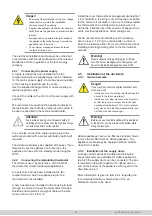
Connecting the power supply
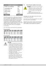
A 3-pole terminal has been installed in the fan
compartment where a supplied plug can be installed
for the mains power supply. A hole has been included
in the housing to lead through the cable.
Use the supplied blind grommet or cable coupling to
lead through the cable.
Connect the cable to the 230 V~AC power supply with
earthing.
We recommend connecting the appliance directly to
the distribution box that has a delay fuse (the value to
be used is speci
fi
ed in the technical data table).
Attention!
We recommend using circuit breakers with a D
switching-off curve because of the high input surge
currents of the direct current motors.
You can also connect the cable using a plug to the
wall socket outlet with a socket with safety earthing if
required.
The Udara must always be supplied with power. If you
temporarily put the appliance out of service, the
appliance can be set to the standby mode using the
RC21.
4.4.2
Connecting the modulating thermostat
The Udara is used, by preference, with the RC21
thermostat for simple residential applications.
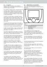
A 2-pole terminal has been installed in the fan
compartment on which a supplied plug for the
thermostat can be installed.
A hole has also been included in the housing to lead
through the cable. Connect the thermostat through a
shielded and twisted 2-core signal cable with a wire
cross-section of 2 x 0.8 mm².
plaats waar deze niet wordt beïnvloed door andere
warmtebronnen zoals uitblaasroosters, elektrische
apparaten, direct zonlicht, enz.
Ook de plaatsing bij vensters, deuren, dicht (<1.20 m)
bij een buitenmuur of onder of dichtbij een trap is niet
aan te bevelen.
Voor meer inlichtingen inzake montage en program-
mering verwijzen wij naar de handleiding van de
thermostaat.
Waarschuwing!
Sluit nooit een spanningsvoerende kamerthermo-
staat aan. De branderautomaat wordt daardoor
onherstelbaar beschadigd.
4.6 Installatie
kanalensysteem
4.6.1 Algemene
opmerkingen
Gevaar!
Indien u het toestel wenst aan te sluiten zonder een
kanalensysteem moet u:
• een rooster op de aanzuigopening plaatsen
die de toegang tot het ventilatorcompartiment
belet.
• een rooster of uitblaasplenum monteren op de
uitblaasopening zodat er geen rechtstreekse
toegang is tot het warmtewisselaarcomparti-
ment. Dit rooster of plenum moet ook verhinde-
ren dat er brandbaar materiaal op de warmte-
wisselaar kan vallen.
Waarschuwing!
Alvorens u de Udara upfl ow gebruikt met terugname
onderaan, moet u de bodemplaat verwijderen langs-
heen de uitsparingen.
In de Udara toestellen is er standaard een lucht
fi
lter
voorzien. Verwijder nooit het lucht
fi
lter uit een Udara
toestel. Het apparaat dient steeds voorzien te zijn van
een lucht
fi
lter klasse EU3 of beter.
4.6.2 Installatie
aanvoerkanalen
Voor de Udara toestellen is een gamma van witgelakte
akoestisch geïsoleerde luchtverdeelkasten (plenums)
beschikbaar waar de toevoerkanalen op kunnen wor-
den aangesloten. Deze worden bij een bovenuitbla-
zende versie op, bij een onderuitblazende versie onder
het toestel geplaatst.
In punt 4.6.4 vindt meer informatie aangaande de
aanbevolen minimale afmetingen van de te gebruiken
luchtverdeelkasten.
Install the room thermostat at an approximate height of
1.6 m centrally in the living room and easily accessible
for the normal air circulation in the room. Always install
the thermostat on an inside wall at a place where it
will not be in
fl
uenced by other sources of heat such as
vents, electrical appliances, direct sunlight, etc.
We do not recommend installing next to windows,
doors, close (< 1.20 m) to outside walls or under or
close to a staircase either. For more information about
installing and programming refer to the thermostat’s
manual.
Warning!
Never connect a voltage-carrying room thermo-
stat. The burner management control system will
become irreparably damaged because of this.
4.5
Installation of the ductwork
4.5.1 General
remarks
Danger!
If you want to connect the appliance without duct-
work, you must:
• install a vent on the suction inlet that stops the
access to the fan compartment;
• install a vent or blow plenum on the blow hole
so that there is no direct access to the heat
exchanger compartment. This vent or plenum
must also ensure that
fl
ammable material can-
not fall on the heat exchanger.
Warning!
Before you use the Udara upfl ow with readmission
at the bottom, you must remove the bottom plate
along the recesses.
Udara appliances have an air
fi
lter as standard. Never
remove the air
fi
lter from an Udara appliance. The
appliance must always be equipped with an air
fi
lter
class EU3 or better.
4.5.2
Installation of the supply ducts
A range of white acoustic insulated air distribution
boxes (plenums) are available for Udara appliances
to which the supply ducts can be connected. The box
is installed on top with regard to the up
fl
ow version
and on the bottom of the appliance with regard to the
down
fl
ow version.
More information is given in item 4.6.4 regarding the
recommended minimum dimensions of the air
distribution boxes to be used.


