background image


2


Welcome to the 

μ

PA 


The 

μ

PA

 micro preamplifier with 16 or 32 electrode inputs is connected to the microelectrode probes  

for providing the initial tenfold amplification stage. Gain might be different from default value 
according to customer specification. The use of a headstage preamplifier unit optimizes the signal to 
noise ratio. 

The micro preamplifier is equipped with an Omnetics socket for NeuroNexus probes. It has an additional 

common ground

 and a 

reference electrode input

. The reference electrode is ideally identical to the 

recording electrodes and placed into a comparable but inactive area or tissue. Background or noise 
signals that are picked up by both the reference electrode and the recording electrodes are removed. 

The metal case provides 

electrical shielding

The very high input impedance ensures stable long-term 

recordings. 

 
Ideally, the input impedance would be infinite to minimize electrical current. As low voltages are 
generally recorded, a high current would flow if the input impedance were low. As a result, the 
amplifier would not be able to deliver the current, and the voltage would break down.  
 
The micro preamplifier has a high input impedance to avoid this problem. 

Adapters

 for all standard 

microelectrodes

 such as 

NeuroNexus probes

 (from NeuroNexus 

®

) for acute and chronic 

implantations ensure a close proximity to the probe to minimize signal loss and cross talk. Adapters are 
not included in the standard scope of delivery and have to be ordered separately. For custom adapters, 
please ask your local retailer or contact Multi Channel Systems MCS GmbH. 
 
To start working with the 

μ

PA and to learn how to handle the system the 

ME/W Signal Generator  

is a convenient tool. The ME/W Signal Generator can produce analogue signals identical to those from  
a variety of biological samples and is therefore a convenient method to test the functionality of the 
recording system. The ME/W-SG is not included in the standard scope of delivery and has to be ordered 
separately. Please read the ME/W-SG data sheet for more information. 


Summary of Contents for uPA16

Page 1: ...Micro Preamplifier Manual PA16 PA32...

Page 2: ...e publisher and the author be liable for any loss of profit or any other commercial damage caused or alleged to have been caused directly or indirectly by this document 2016 Multi Channel Systems MCS...

Page 3: ...ti Channel Experimenter 6 3 3 Setting up MC_Rack 9 3 3 1 Noise Level Test 9 3 3 2 ME W SG Test 10 3 4 Service and Maintenance 11 3 4 1 Cleaning the Connectors 11 3 4 2 Sterilization 11 4 PA16 12 4 1 P...

Page 4: ...these no later than on conclusion of the contract Multi Channel Systems MCS GmbH makes no Guarantee as to the accuracy of any and all tests and data generated by the use of the device or the software...

Page 5: ...ice may only be used for its intended purpose be used when in a perfect condition Improper use could lead to serious even fatal injuries to the user or third parties and damage to the device itself or...

Page 6: ...As low voltages are generally recorded a high current would flow if the input impedance were low As a result the amplifier would not be able to deliver the current and the voltage would break down Th...

Page 7: ...reference input will be subtracted from the recording signals This will either lead to signal loss or to a very high noise level 1 Ground the animal with a ground electrode of large surface area for...

Page 8: ...rea of the reference though 5 Connect all unused recording channels to the GND input or to the reference electrode if ground and reference are short circuited to avoid picking up noise As the total am...

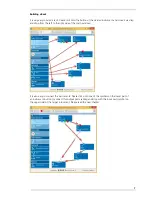
Page 9: ...your virtual rack configuration in the Experiment Setup window which is blank after program start On the left side five classes of instruments are provided Data Sources Recorder and Stimulators are h...

Page 10: ...and drop from the left to the right side of the main window It is also easy to connect the instruments Please click onto one of the symbols on the lower part of an instrument button to connect this ou...

Page 11: ...Data Three color coded output ports of the MEA2100 data acquisition device Example Click on the blue symbol output port of the data source and connect it by drag and drop with the blue symbol input p...

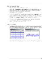
Page 12: ...fier with a gain of 100 the total gain is 1000 4 On the Edit menu click Add Data Display to add a raw data display to your virtual rack 5 In the virtual rack tree view pane select the Display 1 and cl...

Page 13: ...tics connector of the PA is lettered in black and the Omnetics connector of the ME W SG respectively Please connect the devices in this way that the letters are on one side facing to the bottom of the...

Page 14: ...them in an ultrasonic bath for 10 to 20 s Air dry the micro preamplifier for about 5 min before use You can also clean the connectors with distilled water in an ultrasonic bath Dry the connectors wit...

Page 15: ...exus AXIAL NeuroNexus C16 NeuroNexus CM16 NeuroNexus F16 NeuroNexus H16 NeuroNexus HP16 NeuroNexus MRC16 NeuroNexus MRCM16 To connect the following NeuroNexus probes with 32 electrodes you need two PA...

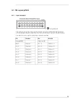
Page 16: ...l housing of the PA16 above The reference input is used for connecting a reference electrode Pin Channel Pin Channel Ground GND Reference REF Pin 1 Channel 1 Pin 9 Channel 9 Pin 2 Channel 2 Pin 10 Cha...

Page 17: ...fier Pin Channel Pin Channel Pin 2 Channel 1 Pin 11 Channel 2 Pin 3 Channel 3 Pin 12 Channel 4 Pin 4 Channel 5 Pin 13 Channel 6 Pin 5 Channel 7 Pin 14 Channel 8 Pin 6 Channel 9 Pin 15 Channel 10 Pin 7...

Page 18: ...Omnetics NSD series A79039 001 female Mating connector type Omnetics NPD series NPD 18 xx GS with 2 guide posts male Output connector type 26 pin HD D Sub male Harting TB 09 56 200 5615 Number of ampl...

Page 19: ...ode Probes for example NeuroNexus CM32 NeuroNexus F32 NeuroNexus H32 NeuroNexus MRCM32 NeuroNexus HP32 To connect the following NeuroNexus probes with 64 electrodes you need two PA32 NeuroNexus H64 Ne...

Page 20: ...EF Pin 20 Channel 18 Pin 3 Channel 1 Pin 21 Channel 19 Pin 4 Channel 2 Pin 22 Channel 20 Pin 5 Channel 3 Pin 23 Channel 21 Pin 6 Channel 4 Pin 24 Channel 22 Pin 7 Channel 5 Pin 25 Channel 23 Pin 8 Cha...

Page 21: ...el 19 Pin 29 Negative supply voltage Pin 8 Channel 22 Pin 30 Positive supply voltage Pin 9 Channel 25 Pin 31 Ground GND Pin 10 Channel 28 Pin 32 Channel 3 Pin 11 Channel 31 Pin 33 Channel 6 Pin 12 Gro...

Page 22: ...01 NSD 36 DD GS with 4 guide posts female Mating connector type Omnetics for example A70001 001 NPD 36 xx GS with 4 guide posts male Output connector type 44 pin HD D Sub male Harting TB 09 56 300 561...

Page 23: ...rum provides an excellent opportunity for you to exchange your experience or thoughts with other users worldwide Mailing list If you have subscribed to the newsletter you will be automatically informe...

Reviews: