6. COMMUNICATIONS
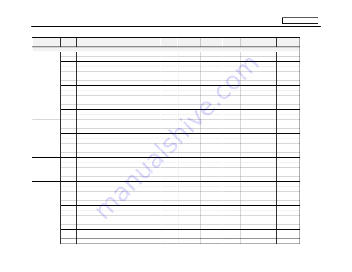
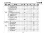
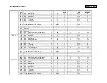
MEMORY MAP
6-27
GROUP
ADDR
(hex)
DESCRIPTION
MIN.
MAX.
STEP
VALUE
UNITS
FORMAT
CODE
FACTORY
DEFAULT
Setpoints (Addresses 1000 -1FFF)
PREFEREN-
1000
Default Message Cycle Time
5
100
5
s
F2
20
CES
1001
Default Message Timeout
10
900
1
s
F1
300
1002
Reserved
1003
Average Motor Load Calculation Period
1
90
1
min
F1
15
1004
Temperature Display Units
0
1
1
-
FC100
0
1005
Trace Memory Trigger Position
1
100
1
%
F1
25
1006
Trace Memory Buffers
1
16
1
cycles
F1
8
1007
Display Update Interval
0.1
6.0
0.1
s
F2
0.4
1008
Cyclic Load Filter Interval
0
32
1
cycles
F1
0
1009
Passcode (Write Only)
0
99999999
1
N/A
F12
0
100B
Encrypted Passcode (Read Only)
N/A
N/A
N/A
N/A
F12
N/A
1008
Reserved
...
100F
Reserved
RS485
1010
Slave Address
1
254
1
-
F1
254
SERIAL
1011
Computer RS485 Baud Rate
0
5
1
-
FC101
4
PORTS
1012
Computer RS485 Parity
0
2
1
-
FC102
0
1013
Auxiliary RS485 Baud Rate
0
5
1
-
FC101
4
1014
Auxiliary RS485 Parity
0
2
1
-
FC102
0
1015
Reserved
...
102F
Reserved
REAL TIME
1030
Date
N/A
N/A
N/A
N/A
F18
N/A
CLOCK
1032
Time
N/A
N/A
N/A
N/A
F19
N/A
1034
Reserved
...
103F
Reserved
DEFAULT
1040
Reserved
MESSAGES
...
105F
Reserved
MESSAGE
1060
1st and 2nd Char of First Scratchpad Message
32
127
1
-
F1
‘Te’
SCRATCHPAD
1061
3rd and 4th Char of First Scratchpad Message
32
127
1
-
F1
‘xt’
...
1073
39th and 40th Char of First Scratchpad Message
32
127
1
-
F1
‘ ‘
1074
Reserved
...
107F
Reserved
1080
1st and 2nd Char of Second Scratchpad Mes-
sage
32
127
1
-
F1
‘Te’
1081
3rd and 4th Char of Second Scratchpad Message
32
127
1
-
F1
‘xt’
Summary of Contents for SR469
Page 7: ......
Page 19: ...2 INSTALLATION MECHANICAL 2 5 2 1 5 TERMINAL LOCATIONS Figure 2 11 TERMINAL LAYOUT...
Page 21: ...2 INSTALLATION ELECTRICAL 2 7 Figure 2 12 TYPICAL WIRING DIAGRAM...
Page 32: ...ELECTRICAL 2 INSTALLATION 2 18 2 2 14 TYPICAL 2 SPEED MOTOR WIRING...
Page 39: ...OVERVIEW 3 SR469 OPERATION 3 6 yy SETPOINTS yy S1 SR469 SETUP...
Page 104: ...4 SETPOINT PROGRAMMING S11 MONITORING 4 65 Figure 4 24 TRIP COIL SUPERVISION...
Page 113: ...S12 ANALOG I O 4 SETPOINT PROGRAMMING 4 74...
Page 244: ...8 469PC PROGRAM WAVEFORM CAPTURE 8 13 Figure 8 11 WAVEFORM CAPTURE...


