MECHANICAL 2.
INSTALLATION
2-4
2.1.4
UNIT WITHDRAWAL AND INSERTION
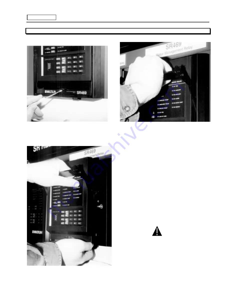
Figure 2-8 PRESS LATCH TO DISENGAGE HANDLE
Figure 2-9 ROTATE HANDLE TO STOP POSITION
Figure 2-10 SLIDE UNIT OUT OF THE CASE
To remove the unit from the case:
(1) Open the cover by grasping the center of the right side and
then pulling the cover, which will rotate about the hinges on the
left.
(2) Release the locking latch, located below the locking handle, by
pressing upward on the latch with the tip of a screwdriver (see
Figure 2-8).
(3) While holding the latch raised, grasp the locking handle in the
center and pull firmly, rotating the handle up from the bottom of the
unit until movement ceases (see Figure 2-9).
(4) Once the handle is released from the locking mechanism, the
unit can freely slide out of the case when pulled by the handle. It
may sometimes be necessary to adjust the handle position slightly
to free the unit (Figure 2-10).
To insert the unit into the case:
(1) Raise the locking handle to the highest position.
(2) Hold the unit immediately in front of the case and align the
rolling guide pins (near the hinges of the locking handle) to the
guide slots on either side of the case.
(3) Slide the unit into the case until the guide pins on the unit have
engaged the guide slots on either side of the case.
CAUTION: If an attempt is made to install a unit into a
non-matching case, the mechanical key will prevent full insertion
of the unit. Do not apply strong force in the following step or dam-
age may result.
(4) Grasp the locking handle from the center and press down
firmly, rotating the handle from the raised position toward the bot-
tom of the unit.
(5) When the unit is fully inserted, the latch will be heard to click,
locking the handle in the final position.
Summary of Contents for SR469
Page 7: ......
Page 19: ...2 INSTALLATION MECHANICAL 2 5 2 1 5 TERMINAL LOCATIONS Figure 2 11 TERMINAL LAYOUT...
Page 21: ...2 INSTALLATION ELECTRICAL 2 7 Figure 2 12 TYPICAL WIRING DIAGRAM...
Page 32: ...ELECTRICAL 2 INSTALLATION 2 18 2 2 14 TYPICAL 2 SPEED MOTOR WIRING...
Page 39: ...OVERVIEW 3 SR469 OPERATION 3 6 yy SETPOINTS yy S1 SR469 SETUP...
Page 104: ...4 SETPOINT PROGRAMMING S11 MONITORING 4 65 Figure 4 24 TRIP COIL SUPERVISION...
Page 113: ...S12 ANALOG I O 4 SETPOINT PROGRAMMING 4 74...
Page 244: ...8 469PC PROGRAM WAVEFORM CAPTURE 8 13 Figure 8 11 WAVEFORM CAPTURE...


