2. INSTALLATION
ELECTRICAL
2-9
2.2.4
GROUND CURRENT INPUT
The SR469 has a dual primary isolating transformer for ground CT connection. There are no internal ground connections on the ground
current inputs. The ground CT circuits are shorted by automatic mechanisms on the SR469 case if the unit is withdrawn. The 1A/5A tap is
used either for zero sequence/core balance applications (see Figure 2-12) or residual ground connections where the summation of the three
phase current CTs is passed through the ground current input (see Figure 2-14). The maximum ground CT primary current is 5000 A for the
1A/5A tap. Alternatively, the 50:0.025 ground CT input has been designed for sensitive ground current detection on high resistance grounded
systems where the Multilin 50:0.025 core balance CT is to be used. In applications such as mines, where earth leakage current must be
measured for personnel safety, primary ground current as low as 0.25A may be detected with the Multilin 50:0.025 CT. Only one ground CT
input tap should be used on a given unit.
The SR469 will measure up to 5 A secondary current if the 1A/5A
tap is used. Since the conversion range is relatively small, the 1A
or 5A option is field programmable. Proper selection of this
setpoint will ensure proper reading of primary ground current. The
1A/5A ground CT chosen must be capable of driving the SR469
ground CT burden (see Specifications for ratings). The SR469 will
measure up to 25A of primary ground current if this tap is used in
conjunction with the Multilin core balance CT.
NOTE: The zero sequence connection is recommended. Unequal
saturation of CTs, size and location of motor, resistance of
power system and motor core saturation density, etc. may
cause false readings in the residually connected GF
circuit.
NOTE: Only one ground input should be wired and the other
input should be unconnected.
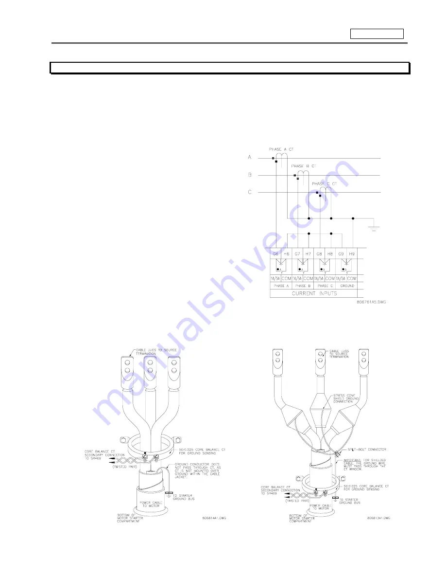
Figure 2-14 RESIDUAL GROUND CT CONNECTION
The exact placement of a zero sequence CT, so that only ground fault current will be detected, is shown in Figure 2-15. If the core balance
CT is placed over shielded cable, capacitive coupling of phase current into the cable shield during motor starts may be detected as ground
current unless the shield wire is also passed through the CT window. Twisted pair cabling on the zero sequence CT is recommended.
Figure 2-15 CORE BALANCE GROUND CT INSTALLATION
Summary of Contents for SR469
Page 7: ......
Page 19: ...2 INSTALLATION MECHANICAL 2 5 2 1 5 TERMINAL LOCATIONS Figure 2 11 TERMINAL LAYOUT...
Page 21: ...2 INSTALLATION ELECTRICAL 2 7 Figure 2 12 TYPICAL WIRING DIAGRAM...
Page 32: ...ELECTRICAL 2 INSTALLATION 2 18 2 2 14 TYPICAL 2 SPEED MOTOR WIRING...
Page 39: ...OVERVIEW 3 SR469 OPERATION 3 6 yy SETPOINTS yy S1 SR469 SETUP...
Page 104: ...4 SETPOINT PROGRAMMING S11 MONITORING 4 65 Figure 4 24 TRIP COIL SUPERVISION...
Page 113: ...S12 ANALOG I O 4 SETPOINT PROGRAMMING 4 74...
Page 244: ...8 469PC PROGRAM WAVEFORM CAPTURE 8 13 Figure 8 11 WAVEFORM CAPTURE...


