2. INSTALLATION
ELECTRICAL
2-13
2.2.10
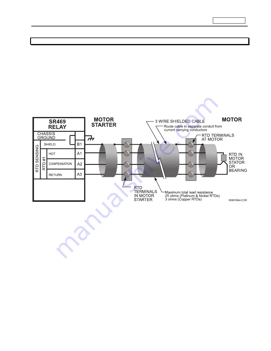
RTD SENSOR CONNECTIONS
The SR469 can monitor up to 12 RTD inputs for Stator, Bearing, Ambient, or Other temperature monitoring. The type of each RTD is field
programmable as: 100
Ω
Platinum (DIN.43760), 100
Ω
Nickel, 120
Ω
Nickel, or 10
Ω
Copper. RTDs must be three wire type. Every two
RTDs shares a common return.
The SR469 RTD circuitry compensates for lead resistance, provided that each of the three leads is the same length. Lead resistance
should not exceed 25
Ω
per lead for platinum and nickel type RTDs or 3
Ω
per lead for Copper type RTDs. Shielded cable should be used
to prevent noise pickup in the industrial environment. RTD cables should be kept close to grounded metal casings and avoid areas of
high electromagnetic or radio interference. RTD leads should not be run adjacent to or in the same conduit as high current carrying
wires.
Figure 2-21 RTD WIRING
IMPORTANT: The RTD circuitry is isolated as a group with the Analog Input circuitry and the Analog Output circuitry. Only one ground
reference should be used for the three circuits. Transorbs limit this isolation to
±
36 volts with respect to the SR469 safety ground.
Summary of Contents for SR469
Page 7: ......
Page 19: ...2 INSTALLATION MECHANICAL 2 5 2 1 5 TERMINAL LOCATIONS Figure 2 11 TERMINAL LAYOUT...
Page 21: ...2 INSTALLATION ELECTRICAL 2 7 Figure 2 12 TYPICAL WIRING DIAGRAM...
Page 32: ...ELECTRICAL 2 INSTALLATION 2 18 2 2 14 TYPICAL 2 SPEED MOTOR WIRING...
Page 39: ...OVERVIEW 3 SR469 OPERATION 3 6 yy SETPOINTS yy S1 SR469 SETUP...
Page 104: ...4 SETPOINT PROGRAMMING S11 MONITORING 4 65 Figure 4 24 TRIP COIL SUPERVISION...
Page 113: ...S12 ANALOG I O 4 SETPOINT PROGRAMMING 4 74...
Page 244: ...8 469PC PROGRAM WAVEFORM CAPTURE 8 13 Figure 8 11 WAVEFORM CAPTURE...


