4. SETPOINT PROGRAMMING
S2 SYSTEM SETUP
4-11
4.3 S2 SYSTEM SETUP
4.3.1
CURRENT SENSING
y
#
&855(17
#
6(16,1*
y
#
>(17(5@
#
IRU
#
PRUH
Õ
Õ
Õ
Õ
ENTER
ENTER
ENTER
ENTER
ESCAPE
ESCAPE
ESCAPE
ESCAPE
Ö
Ö
Ö
Ö
3+$6(
#
&7
#
35,0$5<
=
1RW
#
3URJUDPPHG
B1>75*ð!ã% äð>_dð@b_WbQ]]UT
CD5@*ð!
Û
Û
Û
Û
ESCAPE
ESCAPE
ESCAPE
ESCAPE
MESSAGE
MESSAGE
MESSAGE
MESSAGE
Ú
Ú
Ú
Ú
02725
#
)8//
#
/2$'
#
$036
)/$
=#
1RW
#
3URJUDPPHG
B1>75*ð!ã% äð>_dð@b_WbQ]]UT
CD5@*ð!
Û
Û
Û
Û
ESCAPE
ESCAPE
ESCAPE
ESCAPE
MESSAGE
MESSAGE
MESSAGE
MESSAGE
Ú
Ú
Ú
Ú
*5281'
#
&7
#=
0XOWLOLQ
#83=31358
B1>75*ð>_^Uäð!1ðCUS_^TQbiäð%1ðCUS_^TQbiäð=e\dY\Y^ð% * â "%
Û
Û
Û
Û
ESCAPE
ESCAPE
ESCAPE
ESCAPE
MESSAGE
MESSAGE
MESSAGE
MESSAGE
Ú
Ú
Ú
Ú
*5281'
#
&7
#
35,0$5<
=
433#
$
B1>75*ð!ã% äðCD5@*ð!
>?D5*ðdXYcð]UccQWUðcUU^ð_^\iðYVðdXUð7b_e^Tð3DðcU\USdY_^ðQR_fUðYcð!1ð_bð%1ðCUS_^TQbi
Û
Û
Û
Û
ESCAPE
ESCAPE
ESCAPE
ESCAPE
MESSAGE
MESSAGE
MESSAGE
MESSAGE
Ú
Ú
Ú
Ú
3+$6(
#
',))(5(17,$/
&7
=#
1RQH
B1>75*ð>_^Uäð!1ðCUS_^TQbiäð%1ðCUS_^TQbi
Û
Û
Û
Û
ESCAPE
ESCAPE
ESCAPE
ESCAPE
MESSAGE
MESSAGE
MESSAGE
MESSAGE
Ú
Ú
Ú
Ú
3+$6(
#
',))(5(17,$/
&7
#
35,0$5<
=#433#
$
B1>75*ð!ðãð% äððCD5@*ð!
>?D5*ðdXYcð]UccQWUðcUU^ð_^\iðYVðdXUð4YVVUbU^dYQ\ð3DðcU\USdY_^ðQR_fUðYcð!1ð_bð%1ðCUS_^TQbi
Û
Û
Û
Û
ESCAPE
ESCAPE
ESCAPE
ESCAPE
MESSAGE
MESSAGE
MESSAGE
MESSAGE
Ú
Ú
Ú
Ú
(1$%/(
#50
63(('
#
02725
3527(&7,21
=#
1R
B1>75*ððIUcäð>_
Û
Û
Û
Û
ESCAPE
ESCAPE
ESCAPE
ESCAPE
MESSAGE
MESSAGE
MESSAGE
MESSAGE
Ú
Ú
Ú
Ú
63(('
5#
3+$6(
#
&7
35,0$5<
=#433#
$
B1>75*ð!ðãð%
CD5@*!
>?D5*ðdXYcð]UccQWUðcUU^ð_^\iðYVðdXUð"ãC`UUTð]_d_bð`b_dUSdY_^ðYcðU^QR\UT
Û
Û
Û
Û
ESCAPE
ESCAPE
ESCAPE
ESCAPE
MESSAGE
MESSAGE
MESSAGE
MESSAGE
×
×
×
×
63(('
5#
02725
)/$
=#4#
$
B1>75*ð!ðãð% äððCD5@*ð!
>?D5*ðdXYcð]UccQWUðcUU^ð_^\iðYVðdXUð"ãC`UUTð]_d_bð`b_dUSdY_^ðYcðU^QR\UT
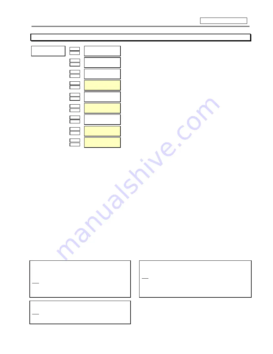
FUNCTION:
As a safeguard, when a unit is received from the factory, the Phase CT primary and Motor FLA will be defaulted to ‘Not Programmed’. A
block start will indicate that the SR469 was never programmed. Once Phase CT Primary and Motor FLA are entered, the alarm will reset
itself. The phase CT should be chosen such that the FLA is no less than 50 % of the rated phase CT primary. Ideally, the phase CT
primary should be chosen such that the FLA is 100 % of the phase CT primary or slightly less, never more. The secondary value of 1 or
5 amps must be specified at the time of order, so that the proper hardware will be installed. A value for Motor Full Load Amps (FLA)
must also be entered. The value may be taken from the motor nameplate or motor data sheets. Service Factor may be entered as
Overload Pickup, described later (S5 PROTECTION under THERMAL MODEL).
For high resistance grounded systems, sensitive ground current detection is possible if the 50/.025 ground CT input is used. To use the
50/.025 input, select Multilin 50/.025 for the GROUND CT setpoint. No additional ground CT messages will appear. On solidly grounded
systems, where fault currents may be quite large, the SR469 1A or 5A secondary ground CT input should be used for either Zero Se-
quence or Residual ground sensing. If the connection is Residual, the Ground CT Secondary and Primary values should be the same
as the phase CT. If however, the connection is Zero Sequence, the Ground CT Secondary and Primary values must be entered. The
Ground CT primary should be selected such that potential fault current does not exceed 20 times the primary rating. When relaying class
CTs are purchased, this precaution will ensure that the Ground CT does not saturate under fault conditions.
A value for Differential CT Primary must be entered if the differential feature is to be used. If two CTs are used per phase in a vectorial
summation configuration, the CTs should be chosen to ensure there is no saturation during motor starting. If however, a core balance
CT is used for the differential protection in each phase, a low CT rating of 50 or 100 A allows for very sensitive differential protection.
When the 2-Speed motor feature is used, a value for a second set of Phase CTs and motor FLA must be entered here for Speed 2. If
the Phase CTs are the same as the speed 1 phase CTs, simply enter the same value here as well.
EXAMPLE:
Motor Nameplate FLA: 87 A
Low Resistance Grounded, Maximum Fault: 400 A
SR469 purchased with 5 A phase CT Secondary
Ground Fault Detection to be Residual
Set: Phase CT Primary: 100
Motor Full Load Amps: 87
Ground CT: 5 A Secondary
Ground CT Primary: 100
Motor Nameplate FLA: 255 A
Solidly Grounded, Maximum Fault: 10000 A
Zero Sequence Ground CT: (10000/20) 500:1
Set:
Phase CT Primary: 300
Motor Full Load Amps: 255
Ground CT: 5 A Secondary
Ground CT Primary: 500
Motor Nameplate FLA: 330 A
High Resistance Grounded, Maximum Fault: 5 A
Set: Phase CT Primary: 350
Motor Full Load Amps: 330
Ground CT: Multilin 50/.025
Summary of Contents for SR469
Page 7: ......
Page 19: ...2 INSTALLATION MECHANICAL 2 5 2 1 5 TERMINAL LOCATIONS Figure 2 11 TERMINAL LAYOUT...
Page 21: ...2 INSTALLATION ELECTRICAL 2 7 Figure 2 12 TYPICAL WIRING DIAGRAM...
Page 32: ...ELECTRICAL 2 INSTALLATION 2 18 2 2 14 TYPICAL 2 SPEED MOTOR WIRING...
Page 39: ...OVERVIEW 3 SR469 OPERATION 3 6 yy SETPOINTS yy S1 SR469 SETUP...
Page 104: ...4 SETPOINT PROGRAMMING S11 MONITORING 4 65 Figure 4 24 TRIP COIL SUPERVISION...
Page 113: ...S12 ANALOG I O 4 SETPOINT PROGRAMMING 4 74...
Page 244: ...8 469PC PROGRAM WAVEFORM CAPTURE 8 13 Figure 8 11 WAVEFORM CAPTURE...


