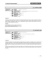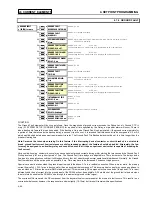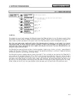
S5 THERMAL MODEL
4. SETPOINT PROGRAMMING
4-30
Table 4-2 SR469 STANDARD OVERLOAD CURVES
PICKUP
STANDARD CURVE MULTIPLIERS
LEVEL
(x FLA)
x 1
x 2
x 3
x 4
x 5
x 6
x 7
x 8
x 9
x 10
x 11
x 12
x 13
x 14
x 15
1.01
4353.6 8707.2 13061
17414
21768
26122
30475
34829
39183
43536
47890
52243
56597
60951
65304
1.05
853.71 1707.4 2561.1 3414.9 4268.6 5122.3 5976.0 6829.7 7683.4 8537.1 9390.8 10245
11098
11952
12806
1.10
416.68 833.36 1250.0 1666.7 2083.4 2500.1 2916.8 3333.5 3750.1 4166.8 4583.5 5000.2 5416.9 5833.6 6250.2
1.20
198.86 397.72 596.58 795.44 994.30 1193.2 1392.0 1590.9 1789.7 1988.6 2187.5 2386.3 2585.2 2784.1 2982.9
1.30
126.80 253.61 380.41 507.22 634.02 760.82 887.63 1014.4 1141.2 1268.0 1394.8 1521.6 1648.5 1775.3 1902.1
1.40
91.14
182.27 273.41 364.55 455.68 546.82 637.96 729.09 820.23 911.37 1002.5 1093.6 1184.8 1275.9 1367.0
1.50
69.99
139.98 209.97 279.96 349.95 419.94 489.93 559.92 629.91 699.90 769.89 839.88 909.87 979.86 1049.9
1.75
42.41
84.83
127.24 169.66 212.07 254.49 296.90 339.32 381.73 424.15 466.56 508.98 551.39 593.81 636.22
2.00
29.16
58.32
87.47
116.63 145.79 174.95 204.11 233.26 262.42 291.58 320.74 349.90 379.05 408.21 437.37
2.25
21.53
43.06
64.59
86.12
107.65 129.18 150.72 172.25 193.78 215.31 236.84 258.37 279.90 301.43 322.96
2.50
16.66
33.32
49.98
66.64
83.30
99.96
116.62 133.28 149.94 166.60 183.26 199.92 216.58 233.24 249.90
2.75
13.33
26.65
39.98
53.31
66.64
79.96
93.29
106.62 119.95 133.27 146.60 159.93 173.25 186.58 199.91
3.00
10.93
21.86
32.80
43.73
54.66
65.59
76.52
87.46
98.39
109.32 120.25 131.19 142.12 153.05 163.98
3.25
9.15
18.29
27.44
36.58
45.73
54.87
64.02
73.16
82.31
91.46
100.60 109.75 118.89 128.04 137.18
3.50
7.77
15.55
23.32
31.09
38.87
46.64
54.41
62.19
69.96
77.73
85.51
93.28
101.05 108.83 116.60
3.75
6.69
13.39
20.08
26.78
33.47
40.17
46.86
53.56
60.25
66.95
73.64
80.34
87.03
93.73
100.42
4.00
5.83
11.66
17.49
23.32
29.15
34.98
40.81
46.64
52.47
58.30
64.13
69.96
75.79
81.62
87.45
4.25
5.12
10.25
15.37
20.50
25.62
30.75
35.87
41.00
46.12
51.25
56.37
61.50
66.62
71.75
76.87
4.50
4.54
9.08
13.63
18.17
22.71
27.25
31.80
36.34
40.88
45.42
49.97
54.51
59.05
63.59
68.14
4.75
4.06
8.11
12.17
16.22
20.28
24.33
28.39
32.44
36.50
40.55
44.61
48.66
52.72
56.77
60.83
5.00
3.64
7.29
10.93
14.57
18.22
21.86
25.50
29.15
32.79
36.43
40.08
43.72
47.36
51.01
54.65
5.50
2.99
5.98
8.97
11.96
14.95
17.94
20.93
23.91
26.90
29.89
32.88
35.87
38.86
41.85
44.84
6.00
2.50
5.00
7.49
9.99
12.49
14.99
17.49
19.99
22.48
24.98
27.48
29.98
32.48
34.97
37.47
6.50
2.12
4.24
6.36
8.48
10.60
12.72
14.84
16.96
19.08
21.20
23.32
25.44
27.55
29.67
31.79
7.00
1.82
3.64
5.46
7.29
9.11
10.93
12.75
14.57
16.39
18.21
20.04
21.86
23.68
25.50
27.32
7.50
1.58
3.16
4.75
6.33
7.91
9.49
11.08
12.66
14.24
15.82
17.41
18.99
20.57
22.15
23.74
8.00
1.39
2.78
4.16
5.55
6.94
8.33
9.71
11.10
12.49
13.88
15.27
16.65
18.04
19.43
20.82
10.00
1.39
2.78
4.16
5.55
6.94
8.33
9.71
11.10
12.49
13.88
15.27
16.65
18.04
19.43
20.82
15.00
1.39
2.78
4.16
5.55
6.94
8.33
9.71
11.10
12.49
13.88
15.27
16.65
18.04
19.43
20.82
NOTE: Above 8.0 x Pickup, the trip time for 8.0 is used.
This prevents the overload curve from acting as an instantaneous element
Standard Overload Curves Equation:
Time_ To_ Trip
Curve_ Multiplier
2.2116623
0.025303373 (Pickup 1)
0.050547581 (Pickup 1)
2
=
×
×
−
+
×
−
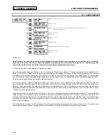
CUSTOM OVERLOAD CURVE
If the motor starting current does begin to infringe on the thermal damage curves, it may become necessary to use a custom curve to
tailor the protection to the motor so that successful starting may be possible without compromising motor protection. Furthermore, the
characteristics of the starting thermal damage curve (locked rotor and acceleration) and the running thermal damage curves may not fit
together very smoothly. In this instance, it may become necessary to use a custom curve to tailor the motor protection to the motor
thermal limits such that the motor may be started successfully and the motor may be utilized to its full potential without compromising
protection. The distinct parts of the thermal limit curves now become more critical. For these conditions, it is recommended that the
SR469 custom curve thermal model be used. The custom overload curve of the SR469 allows the user to program his own curve by
entering trip times for 30 pre-determined current levels.
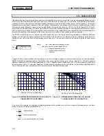
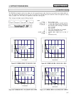
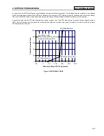
It can be seen in Figure 4-9 that if the running overload thermal limit curve were smoothed into one curve with the locked rotor overload
curve, the motor could not start at 80% line voltage. A custom curve is required.
Summary of Contents for SR469
Page 7: ......
Page 19: ...2 INSTALLATION MECHANICAL 2 5 2 1 5 TERMINAL LOCATIONS Figure 2 11 TERMINAL LAYOUT...
Page 21: ...2 INSTALLATION ELECTRICAL 2 7 Figure 2 12 TYPICAL WIRING DIAGRAM...
Page 32: ...ELECTRICAL 2 INSTALLATION 2 18 2 2 14 TYPICAL 2 SPEED MOTOR WIRING...
Page 39: ...OVERVIEW 3 SR469 OPERATION 3 6 yy SETPOINTS yy S1 SR469 SETUP...
Page 104: ...4 SETPOINT PROGRAMMING S11 MONITORING 4 65 Figure 4 24 TRIP COIL SUPERVISION...
Page 113: ...S12 ANALOG I O 4 SETPOINT PROGRAMMING 4 74...
Page 244: ...8 469PC PROGRAM WAVEFORM CAPTURE 8 13 Figure 8 11 WAVEFORM CAPTURE...


