S7 MOTOR STARTING
4. SETPOINT PROGRAMMING
4-46
4.8.1
ACCELERATION TIMER
y
#
$&&(/(5$7,21
7,0(5
y
#
>(17(5@
#
IRU
#
PRUH
Õ
Õ
Õ
Õ
ENTER
ENTER
ENTER
ENTER
ESCAPE
ESCAPE
ESCAPE
ESCAPE
Ö
Ö
Ö
Ö
$&&(/(5$7,21
#
7,0(5
75,3
=#
2II
B1>75*ð?VVäð<QdSXUTäðE^\QdSXUT
Û
Û
Û
Û
ESCAPE
ESCAPE
ESCAPE
ESCAPE
MESSAGE
MESSAGE
MESSAGE
MESSAGE
Ú
Ú
Ú
Ú
$66,*1
#
75,3
#
5(/$<6
=
7ULS
B1>75*ðDbY`äðDbY`ðêð1ehY\YQbið"äðDbY`ðêð1eh"ðêð1eh#äðDbY`ðêð1ehY\YQbi#
Û
Û
Û
Û
ESCAPE
ESCAPE
ESCAPE
ESCAPE
MESSAGE
MESSAGE
MESSAGE
MESSAGE
×
×
×
×
$&&(/(5$7,21
#
7,0(5
)520
#
67$57
=#4313#
V
B1>75*ð!â ðãð"% â
CD5@*ð â!
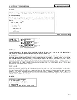
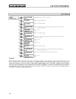
FUNCTION:
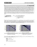
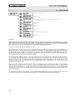
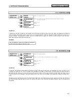
The SR469 Thermal Model is designed to protect the motor under both starting and overload conditions. The Acceleration Timer trip
feature may be used in addition to that protection. If for example, the motor should always start in 2 seconds, but the safe stall time is 8
seconds, there is no point letting the motor remain in a stall condition for 7 or 8 seconds when the thermal model would take it off line.
Furthermore, the starting torque applied to the driven equipment for that period of time could cause severe damage.
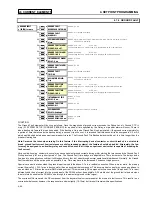
If enabled , the Acceleration Timer trip element will function as follows: A motor start is assumed to be occurring when the SR469 meas-
ures the transition of no motor current to some value of motor current. Typically current will rise quickly to a value in excess of FLA
(e.g. 6 x FLA). At this point, the Acceleration Timer will be initialized with the entered value in seconds. If the current does not fall below
the overload curve pickup level before the timer expires, an acceleration trip will occur. If the acceleration time of the motor is variable,
this feature should be set just beyond the longest acceleration time.
Note: Some motor softstarters may allow current to ramp up slowly while others may limit current to less than Full Load Amps
throughout the start. In these cases, as a generic relay that must protect all motors, the SR469 cannot differentiate between a
motor that has a slow ramp up time and one that has completed a start and gone into an overload condition. Therefore, if the
motor current does not rise to greater than full load within 1 second on start, the acceleration timer feature is ignored. In any
case, the motor is still protected by the overload curve.
4.8.2 START INHIBIT
y
#
67$57
#
,1+,%,7
y
#
>(17(5@
#
IRU
#
PRUH
Õ
Õ
Õ
Õ
ENTER
ENTER
ENTER
ENTER
ESCAPE
ESCAPE
ESCAPE
ESCAPE
Ö
Ö
Ö
Ö
67$57
#
,1+,%,7
%/2&.
=#
2II
5$1*(
=#
2Q
/#
2II
ENTER
ENTER
ENTER
ENTER
ESCAPE
ESCAPE
ESCAPE
ESCAPE
7&
#
86('
0$5*,1
=##58#(
5$1*(
=#3#0#58
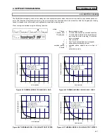
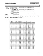
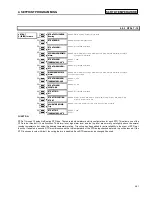
FUNCTION:
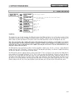
The Start Inhibit feature is intended to help prevent tripping of the motor during start if there is insufficient thermal capacity for a start.
The largest value of thermal capacity used from the last five successful starts is multiplied by (1 + TC USED MARGIN) and stored as
thermal capacity used on start. This thermal capacity margin is used to ensure that a motor start will be successful. If the number is
greater than 100% , 100% is stored as thermal capacity used on start. A successful motor start is one in which phase current rises from
0 to greater than overload pickup and then, after acceleration, falls below the overload curve pickup level. If the Start Inhibit feature is
enabled, each time the motor is stopped, the amount of thermal capacity available (100% - Thermal Capacity Used) is compared to the
Thermal Capacity Used On Start. If the thermal capacity available does not exceed the Thermal Capacity Used On Start, or is not equal
to 100 %, the Start Inhibit Block will become active until there is sufficient thermal capacity. When a block occurs, the lockout time will
be equal to the time required for the motor to cool to an acceptable temperature for a start. This time will be a function of the Cool Time
Constant Stopped programmed at S5 THERMAL MODEL.
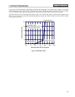
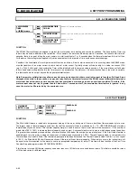
If this feature is turned Off, thermal capacity used must reduce to 15% before an overload lockout resets. This feature should be turned
off if the load varies for different starts.
4.8 S7 MOTOR STARTING
Summary of Contents for SR469
Page 7: ......
Page 19: ...2 INSTALLATION MECHANICAL 2 5 2 1 5 TERMINAL LOCATIONS Figure 2 11 TERMINAL LAYOUT...
Page 21: ...2 INSTALLATION ELECTRICAL 2 7 Figure 2 12 TYPICAL WIRING DIAGRAM...
Page 32: ...ELECTRICAL 2 INSTALLATION 2 18 2 2 14 TYPICAL 2 SPEED MOTOR WIRING...
Page 39: ...OVERVIEW 3 SR469 OPERATION 3 6 yy SETPOINTS yy S1 SR469 SETUP...
Page 104: ...4 SETPOINT PROGRAMMING S11 MONITORING 4 65 Figure 4 24 TRIP COIL SUPERVISION...
Page 113: ...S12 ANALOG I O 4 SETPOINT PROGRAMMING 4 74...
Page 244: ...8 469PC PROGRAM WAVEFORM CAPTURE 8 13 Figure 8 11 WAVEFORM CAPTURE...


