


8
Section 3: Front
Panel Controls, Connections, and Indicators
The front panel of each Smart Tracker contains various connections and indicators. These items are described as follows.
See figures 3-1 for connector locations. Further details regarding use of controls and indicators may be found in the
Startup and Operation
section of this manual.
Controls
:
AC Circuit Breaker: 15Amp circuit breaker protects input and outputs. This circuit breaker is also used as an AC
switch to apply and remove input power to the Smart Tracker. LED illuminates when power is active.
Enter Button: Push button to provide Hot-start and IP reset capabilities. Refer to
Section 5
for user functions.
Connections
:
AC Input Plug: C13/C14 plug and receptacle. Rated at 15Amps.
5-15R Outlet Receptacles: 8, 3 wire outlets used to power devices.
Output Relay Contacts: Phoenix Contact terminal plug. 8 positions per plug. 2 contacts per relay. 12-30 AWG.
Tighten to 5.0 lb-in. Rated for 10A, 250VAC/125VDC.
Input Contacts: Phoenix Contact terminal plug. Optically isolated inputs. 8 positions per plug. 2 contacts per input.
12-30 AWG. Tighten to 5.0 lb-in.
Note
: Do not exceed 5VDC on input.
Analog DC Input Contacts: Phoenix Contact terminal plug. 4 positions per plug. 12-30 AWG. Rated 0-60VDC.
Tighten to 5.0 lb-in.
Temp/Humidity Inputs: Phoenix Contact terminal plug. 4 or 6 positions per plug. 12-30 AWG. Tighten to 5.0 lb-in.
Note
: The external temperature and humidity sensor is an extra cost item.
GPS Antenna Connector: Mini RF, threaded connector for an external antenna.
Ethernet LAN Port: RJ-45 connector: provides connection to network interface.
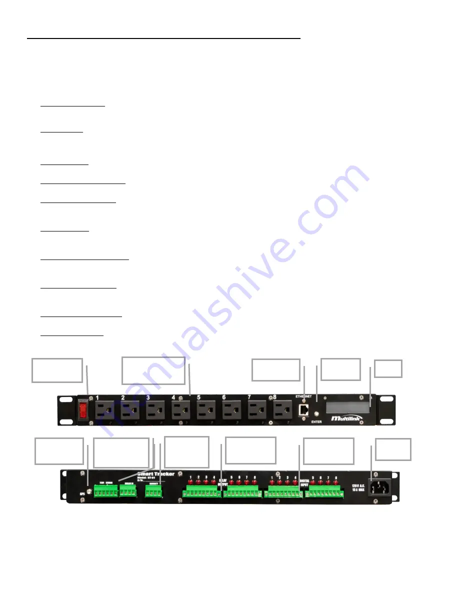
Fig. 3-1 Smart Tracker Front and Rear Detail
PUSH
BUTTON
ETHERNET
PORT
AC CIRCUIT
BREAKER
EIGHT
INDEPENDENT
OUTLETS w/LEDS
LCD
GPS
ANNTENNA
CONNECTOR
EXTERNAL
TEMP AND
HUIMIDITY
TEMPERATURE
AND VDC IN
PLUGS
OUTPUT
RELAYS
w/LEDS
INPUT
CONTACTS
w/LEDS
POWER
PLUG


