background image

Do

cu

men

t N

o.

 O

pti

ma

 16

 Ins

tal

la

tio

n G

ui

de

Contact Us |

North America

Tel:  +1 440 366 6966

Fax:  +1 440 366 6802
Email:  

engsupport@gomultilink.com

Tel:  +1 440 366 6966

Fax:  +1 440 366 6802
Email:  

engsupport@gomultilink.com

Tel:  +1 505 885 02379

Mobile:  +1 505 885 02379
Email:  

bcastro@gomultilink.com

Europe, Middle East & Africa

Latin & South America

Page 1

Visit 

gomultilink.com

 for new product releases!

INST

ALL

ATION

Cop

yr

igh

t ©

 201

9 M

ul

til

in

k I

nc

. A

ll r

igh

ts

 re

se

rv

ed • Sp

eci

fic

at

ion

s s

ub

jec

t t

o ch

an

ge wi

tho

ut

 no

tic

e  •

  Re

v.

 11

/2

0/

201

9  •

  D

oc

ume

nt

 N

o.

 O

pti

m

a 1

6 I

nst

all

at

ion

 G

uid

e

Optima™ 16 Enclosure

General 

3

1. Introduction 

3

1.1 Product Description
1.2 Optima 16               Dimensional Drawing

2. Preparations 

4

2.1 Installation Outline
2.2  Optima 16 Checklist
2.3 Recommended Tools and Equipment

3. General Warnings 

5

3.1 Laser Light Warning
3.2 Laser Light Magnification Warning
3.3 Loose Fiber Warning
3.4 Sharp Edge Warning
3.5 Safety Glasses Warning
3.6 Electrical Shock Warning
3.7 Fiber Damage Warning

4. Installation 

6

Entry Cable Preparations 

6

4.1 Entry Cable Prep
4.2 Cable Jacket Removal
4.3 Cut & Trim CSM
4.4 Armored Cable
4.5 Grounding Kit 

*sold separately

4.6 Connecting the Grounding Braid
4.7 Drill Ground Lug Hole
4.8 Insert Ground Lug
4.9 Secured Grounding

Table of Contents

Table of Contents Continues on Page 2

Summary of Contents for Optima 16

Page 1: ...uide Optima 16 Enclosure General 3 1 Introduction 3 1 1 Product Description 1 2 Optima 16 Dimensional Drawing 2 Preparations 4 2 1 Installation Outline 2 2 Optima 16 Checklist 2 3 Recommended Tools an...

Page 2: ...12 Proper Grommet Seal 4 13 Install CSM Cable Grommet 4 14 Secure Cable to Base 4 15 Fiber Routing Attach Tie Wraps 4 16 Buffer Tube Branching 4 17 Attach Tie Wraps Splicing Buffer Tube to Pigtail 10...

Page 3: ...lateral cable to be connected to single drop cable at another location This guide is for installers who are familiar with fiber optic cable systems and their applications 1 1 Product Description Mult...

Page 4: ...Member Ring cut fiber separation CSM tie down and routing fiber Securing fiber in place to the Optima 16 closure Configuring grommets for cable entry and exit drop Splicing and fiber termination 2 2...

Page 5: ...s of fiber and place on a piece of tape that has been set aside for this purpose 3 4 Sharp Edge Warning The wearing of cut resistant safety gloves to protect your hands from sharp cutting tools and th...

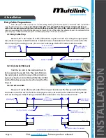
Page 6: ...VIEW CN 01 SEE B O M N A CN 04 27 15 01 N A INITIAL RELEASE Figure 4 1A 4 3 Cut Trim CSM Measure 2 inches from each side of the ring cut locations with the exposed buffer tubes and make a mark on eac...

Page 7: ...on opposite side of ring cut 4 4 Armored Cable Allow at least 1 of the cable s armor to remain from the jacketing Slowly peel back the armor using pliers to separate the seam to allow the wedge from...

Page 8: ...outside of the enclosure to ensure a water tight seal With the long threaded end on the inside of the enclosure attach the ground lug to the base by using the supplied washer and nut s 4 10 Install CS...

Page 9: ...d tie wraps insert into each fiber management clip on the lower side of the base and tighten down enough to hold in place but not directly damage the fiber 4 13 Install CSM Cable Grommet Place the fib...

Page 10: ...o secure your spliced fibers 4 19 Splice Tray Routing Place the completed splice tray within the Optima 16 base Route the branched off buffer tube s accordingly along with how the pigtail slack will b...

Page 11: ...lied tie wraps insert into each fiber management clip on the shell to hold the fiber pigtail 4 21 Attach Splice Tray Cover Before finalizing the splicing section of the Optima 16 attach the splice tra...

Page 12: ...ns Prior to isntallation use sealant to lubricate the outer edge of the grommet for a proper seal In this case we will use blank grommets to seal up the opening Ensure the grommets are inserted into t...

Page 13: ...fiber pigtail is held in place so that the buffer tubes do not get pinched in closing 4 29 Apply Sealant to the Perimeter Before completely shutting the closure flush apply the supplied sealant to the...

Page 14: ...ctions need to be inserted into the supplied foam parking lot 4 33 Latch Cover to Optima Shell Once the sealant has been applied to the gel then close the Optima 16 cover using the plastic latch locat...

Page 15: ...ters additional accessories some of which are included with the Optima S and patch splice options including installable kits and pigtails Mounting Kits Products Description Stock ID Standard Tap Brack...

Page 16: ...0 2019 Page 16 Document No Optima 16 Installation Guide Accessory List Cont Splice Tray Products Description Stock ID 1124 SSTP 072 059 20 Drop Cable Products Description Stock ID OptiDrop Custom Conn...

Page 17: ...NS Copyright 2019 Multilink Inc All rights reserved Specifications subject to change without notice Rev 11 20 2019 Multilink Inc 2019 All Rights Reserved www gomultilink com P R O U D L Y MANUFACTURED...

Reviews: