Visit
for new product releases!
INST
ALL
ATION
Cop
yrigh
t © 2019 Multilink I
nc
. A
ll righ
ts r
eser
ved • Sp
ecific
ations subjec
t t
o change without notic
e • Re
v. 11/20/2019 •
Page 7
Do
cu
men
t N
o.
O
pti
ma
16
Ins
tal
la
tio
n G
ui
de
Installation (Cont.)
4.5 Grounding Kit
*sold separately
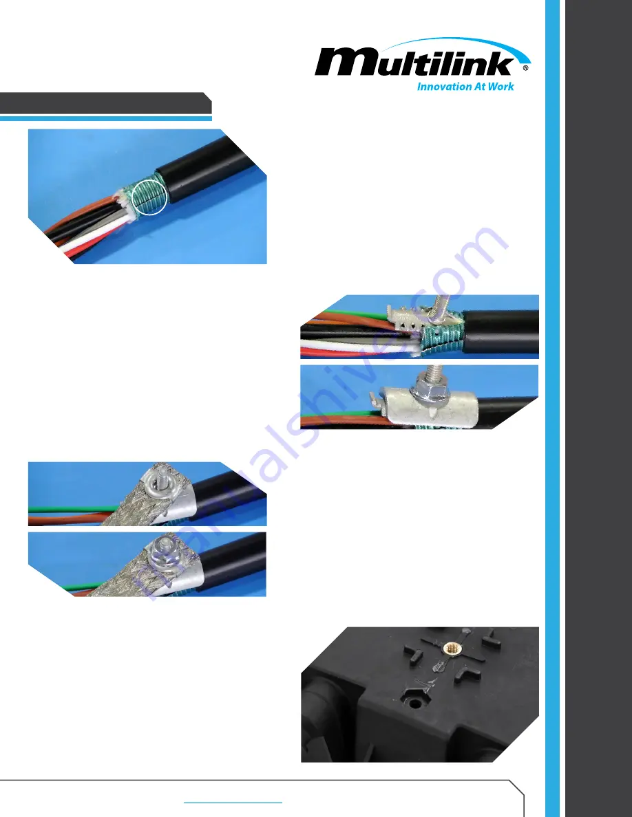
Allow at least 1” of the cable’s armor to
remain from the jacketing. Slowly peel back
the armor using pliers to separate the seam to
allow the wedge* (from the grounding kit,
*sold
separately
) to fit between the buffer tubes and
armor. Repeat on opposite side of ring cut.
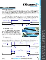
4.4 Armored Cable
Allow at least 1” of the cable’s armor to
remain from the jacketing. Slowly peel back
the armor using pliers to separate the seam to
allow the wedge* (from the grounding kit,
*sold
separately
) to fit between the buffer tubes and
armor. Repeat on opposite side of ring cut.
CABLE ARMOR
SEAM
4.6 Connecting the Grounding Braid
Attach the grounding braid by using the
bolt as a guide. Insert the bolt through the eyelet
and using one of the supplied nuts tighten to
secure the grounding braid to the armored entry
cable. Repeat on opposite side of ring cut.
4.7 Drill Ground Lug Hole
Drill a 0.25” hole into the Optima 16 base
indicated by the cutout on the bottom as shown.


