Page 12
© Multilink Inc. 2021
•
All Rights Reserved
Do
cumen
t N
o. 965-088-10I
nstall
INST
ALL
ATION
Cop
yrigh
t © 2021 Multilink I
nc
. A
ll righ
ts r
eser
ved • Sp
ecific
ations subjec
t t
o change without notic
e • Re
v. 11/16/2021
Do
cumen
t N
o. 965-088-10I
nstall
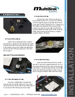
4.25 Splitter & Pigtails
Slide velcro straps through slots on hinged
plate and secure splitter. Remove the adapter
cover and plug-in the pigtail connectors following
the universal fiber color chart. DO NOT remove
the adapter covers all at once.
(Multilink is not
responsible for any fiber loss that may occur if this is
performed improperly.)
4.26 Fiber Drop Grommet
Insert drop cable into fiber drop grommets
and seal with silicone sealant around each drop and
on both inside and outside of grommet. Use silicone
sealant to lubricate the outer edge of the grommet
for a proper seal. Ensure the grommets are inserted
into the bridge in the correct orientation, matching
up the grooves. Secure each drop to the strain
relief bracket using the supplied zip ties to prevent
the fiber from moving and creating an opening in
the sealant. Siliconed pins must be inserted in any
unused slots to prevent leakage.
Installation (Cont.)
1
2
3
4.24 Pigtail & Branch Buffer Tube Routing
Once everything has been successfully
spliced and secured into place make sure the
pigtail fibers and the branched off buffer tube are
routed through the top slot of the cover plate.
Protect the fiber as you close the hinged plate by
guiding the fiber slack into the base.
4.23 Attach Splice Tray Cover
Before finalizing the splicing section of
the Optima™ U attach the splice tray cover on the
hinges of the splice tray base. The cover ensures
that the fiber is safe from the internal buffer tubes
from damaging the fiber itself or causing any
service disruption. If kit comes with metal plate,
secure splice tray with velcro strap from 4.20.
Optima™ U Hinge Plate


