background image

Page 8

© Multilink Inc. 2021  

  All Rights Reserved  

www.gomultilink.com

Do

cumen

t N

o. 965-088-10I

nstall

INST

ALL

ATION

Cop

yrigh

t © 2021 Multilink I

nc

. A

ll righ

ts r

eser

ved  •  Sp

ecific

ations subjec

t t

o change without notic

e  •  Re

v. 11/16/2021

Do

cumen

t N

o. 965-088-10I

nstall

Installation (Cont.)

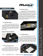
4.9 Secured Grounding

Attach the grounding braid by using the 

ground lug as a guide. Use the appropriate eyelet 

to allow both sides of the ring cut to be mounted 

in the following step. Then attach the additional 

washer and nut to the ground lug to secure the 

braid in place.

4.8 Insert Ground Lug

Drill out the center of the ground lug at 

the specified location in 4.7 with a .25" inch drill. 

Insert the supplied ground lug with the terminal 

lug on the outside of the Optima™ U, compressing 

the rubber seated gasket to the outside of the 

enclosure to ensure a water tight seal. With the 

long threaded end on the inside of the enclosure, 

attach the ground lug to the base by using the 

supplied washer and nut(s).

4.10 Install CSM Clamp

Attach the CSM clamp to the base of the 

Optima™ U using the supplied hardware. Be sure 

to install both clamps on the opposite entry ports 

of the base to accommodate the ring cut. DO NOT 

tighten the CSM clamp all the way down but just 

loose enough to slide the CSM under the clamp.

4.11 Fiber Management Clips

Insert the included fiber management 

clips into the slots of the Optima™ U base in the 

orientation shown. Ensure each clip is fully pushed 

in to prevent it from falling out in later steps. 

Optima™ U Base Installation

Summary of Contents for Optima U

Page 1: ...ilink com Optima U Enclosure General 3 1 Introduction 3 1 1 Product Description 1 2 Optima U Dimensional Drawing 2 Preparations 4 2 1 Installation Outline 2 2 Optima U Checklist 2 3 Recommended Tools...

Page 2: ...4 14 Secure Cable to Base 4 15 Add the Bridge to Lock Assembly 4 16 Fiber Routing Attach Tie Wraps 4 17 Buffer Tube Branching 4 18 Attach Tie Wraps Splicing Buffer Tube to Pigtail 11 4 19 Splice Inpu...

Page 3: ...cable This guide is for installers who are familiar with fiber optic cable systems and their applications 1 1 Product Description Multilink s Optima U enclosure allows a FTTX provider to access the f...

Page 4: ...Removal of cable jacketing and excess CSM Central Strength Member Ring cut fiber separation CSM tie down and routing fiber Securing fiber in place to the Optima U closure Configuring grommets for cab...

Page 5: ...broken cut pieces of fiber and place on a piece of tape that has been set aside for this purpose 3 4 Sharp Edge Warning The wearing of cut resistant safety gloves to protect your hands from sharp cutt...

Page 6: ...T VIEW CN 01 SEE B O M N A CN 04 27 15 01 N A INITIAL RELEASE 64 FOR 72 COUNT or 84 FOR 48 COUNT SHEATH OPENING Figure 4 1 4 3 Cut Trim CSM Measure 2 inches from each side of the ring cut locations wi...

Page 7: ...en the buffer tubes and armor Repeat on opposite side of ring cut 4 4 Armored Cable Once desired length is cut 4 3 remove at least 1 of the cable s outer jacket to expose the armor shielding CABLE ARM...

Page 8: ...Insert the supplied ground lug with the terminal lug on the outside of the Optima U compressing the rubber seated gasket to the outside of the enclosure to ensure a water tight seal With the long thr...

Page 9: ...cut grommet cut side and secure the grommet around the cable Then coat the outside of the feeder port grommet prior to seating in base assembly 4 13 Secure Cable to Base After your fiber is bound via...

Page 10: ...rs 4 18 Attach Tie Wraps Using the supplied tie wraps insert into each fiber management clip on the upper side of the base to hold the branched off buffer tubes Installation Cont 4 16 Install CSM Cabl...

Page 11: ...y Routing Place the completed splice tray within the Optima U base Route the branched off buffer tube s accordingly with how the pigtail slack will be routed 4 19 Splice Input Fiber to Pigtail Followi...

Page 12: ...the grommets are inserted into the bridge in the correct orientation matching up the grooves Secure each drop to the strain relief bracket using the supplied zip ties to prevent the fiber from moving...

Page 13: ...Install Optidrop Fiber Connector Remove the cover from the adapter Then remove the dust cap from the connector and insert the connector into the adapter following the standard fiber color chart An aud...

Page 14: ...ations subject to change without notice Rev 11 16 2021 Document No 965 088 10Install 4 31 Final Bolt Finally secure with bolt on the drop end of enclosure Please note a recommended torque spec of 25 3...

Page 15: ...ma U and patch splice options including installable kits and pigtails Feeder Port Grommets Products Description Stock ID Flat Drop 642 114 10 43 Round 642 113 13 48 Round 642 113 10 58 Round 642 113 1...

Page 16: ...all Surelight Field Installable Kits Products Description Stock ID Tool Kit w Beaver Cleaver 072 656 20 Tool Kit w Precision Cleaver 072 656 21 Accessory List Cont Splice Tray Products Description Sto...

Page 17: ...Tel 1 440 366 6966 Fax 1 440 366 6802 Email engsupport gomultilink com Tel 1 440 366 6966 Mobile 1 440 366 6802 Email lasupport gomultilink com Europe Middle East Africa Latin South America Multilink...

Reviews: