page 22 — DCa25Usi 60 hz generaTor • operaTion anD parTs manUal — rev. #3 (07/19/11)
Output terMinal panel faMiliarizatiOn
Connecting loads
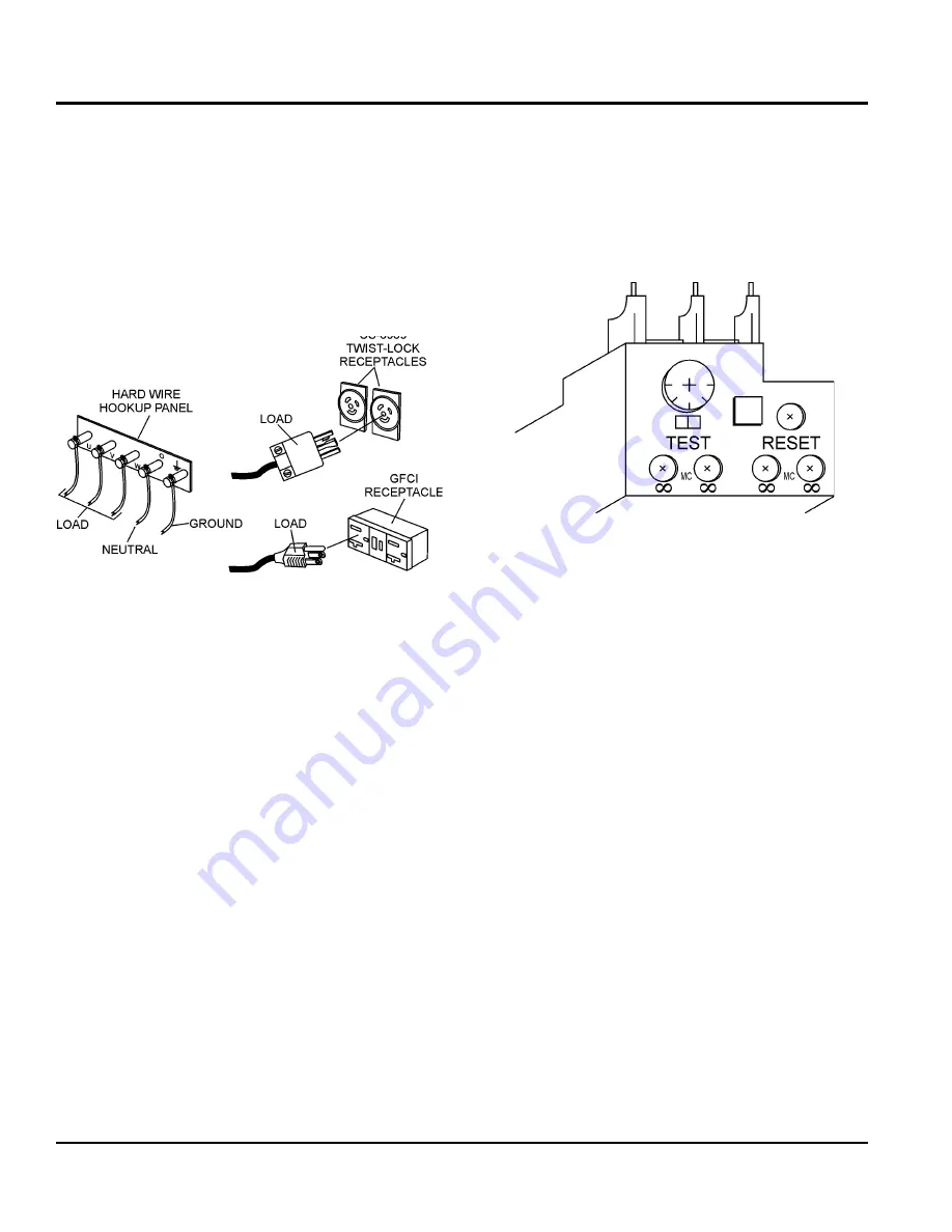
Loads can be connected to the generator by the
output
terminal lugs
or the convenience receptacles (Figure 11).
Make sure to read the operation manual before attempting
to connect a load to the generator.
To protect the output terminals from overload, a 3-pole, 60
amp
main circuit breaker is provided. Make sure to switch
all circuit breakers to the oFF position prior to starting
the engine.
Figure 11. Connecting Loads
over Current relay
An
over current relay (Figure 12) is connected to the main
circuit breaker. In the event of an overload, both the circuit
breaker and the over current relay may trip. If the circuit
breaker can not be reset, the
reset button on the over
current relay must be pressed. The over current relay is
located in the control box.
Figure 12. Over Current Relay
Summary of Contents for DCA5USI
Page 47: ...DCA25usi 60 hz Generator operation and parts manual rev 3 07 19 11 page 47 notes...
Page 50: ...page 50 DCA25Usi 60 hz Generator operation and parts manual rev 3 07 19 11 GENERATOR ASSY...
Page 52: ...page 52 DCA25Usi 60 hz Generator operation and parts manual rev 3 07 19 11 control box ASSY...
Page 54: ...page 54 DCA25Usi 60 hz Generator operation and parts manual rev 3 07 19 11 control box ASSY...
Page 62: ...page 62 DCA25Usi 60 hz Generator operation and parts manual rev 3 07 19 11 BATTERY ASSY...
Page 64: ...page 64 DCA25Usi 60 hz Generator operation and parts manual rev 3 07 19 11 Muffler Assy...
Page 66: ...page 66 DCA25Usi 60 hz Generator operation and parts manual rev 3 07 19 11 FUEL TANK ASSY...
Page 68: ...page 68 DCA25Usi 60 hz Generator operation and parts manual rev 3 07 19 11 ENCLOSURE ASSY...
Page 74: ...page 74 DCA25Usi 60 hz Generator operation and parts manual rev 3 07 19 11 RUBBER SEALS ASSY...
Page 79: ...DCA25usi 60 hz Generator operation and parts manual rev 3 07 19 11 page 79 notes...


