GAC6HR/HRS 60 HZ GENERATOR • OPERATION AND PARTS MANUAL — REV. #1 (12/13/17) — PAGE 21
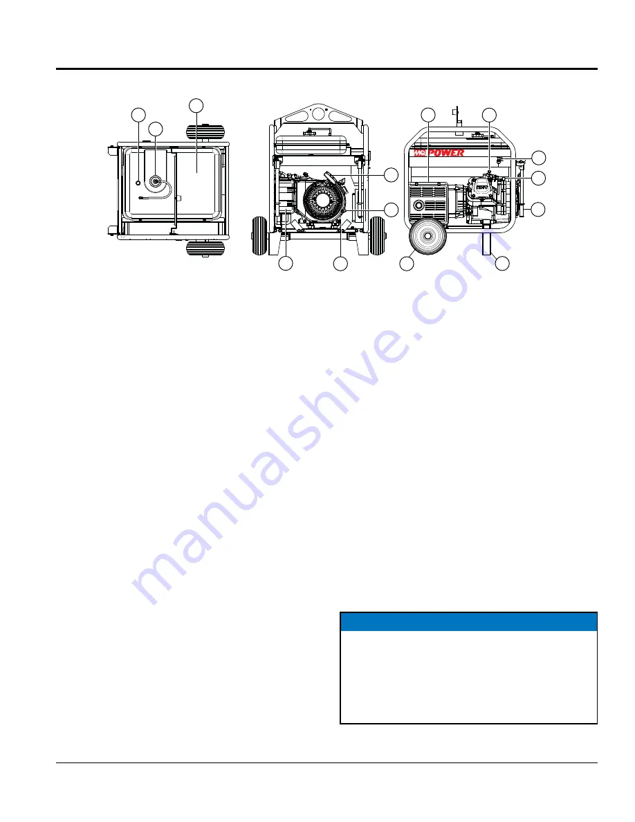
Figure 8. Generator Components (Continued)
15
16
17
21
20
19
18
22
23
24
25
26
28
27
6kW
COMPONENTS (GENERATOR)
15.
Fuel Gauge – This gauge is located on top of the fuel
tank. Read this gauge to determine when fuel is low.
16.
Fuel Tank Cap – Remove this cap to add unleaded
gasoline to the fuel tank. Replenish with clean unleaded
gasoline. Make sure cap is tightened securely.
DO
NOT over fill.
17.
Fuel Tank – Capacity is 5 gallons (19 liters). Fill with
unleaded gasoline.
18.
Recoil Starter (pull rope) – Manual-starting method.
Pull the starter grip until resistance is felt, then pull
briskly and smoothly.
19.
Engine Oil Filler Cap – Remove this cap/dipstick
when the adding of engine oil is required. See Table 2
for recommended type engine oil.
20.
Engine Oil Drain Plug – Remove this drain plug
when draining of the oil from the engine crankcase
is required. Fill with recommended type oil as listed
in Table 4.
21.
Air Cleaner – Prevents dirt and other debris from
entering the fuel system. Unlatch the clips on the side
of the air filter cover to gain access to filter element.
NEVER run the engine without an air cleaner.
22.
Muffler/Heat Shield – Used to reduce noise and
emissions.
NEVER touch this heat shield when the
generator/welder is in use. Always allow time for engine
to cool before servicing.
23.
Spark Plug – Provides spark to the ignition system.
Set spark plug gap to 0.6 - 0.7 mm (0.028 - 0.031 inch).
Clean spark plug once a week.
24.
Fuel Cock Lever –Turn this lever downward to start
(down) the flow of fuel into the carburetor. Turn upward
to stop (up) the flow of fuel.
25.
Choke Lever – Used for starting the engine. Close
the choke lever when starting a cold engine or in
cold weather conditions. The choke enriches the fuel
mixture. Open the choke lever if starting a warm engine
or in warm weather conditions.
26.
Transport Handle (Option) – When transporting of
the generator is required, lift up on each handle and
engage locking pin. Part of wheel kit assembly
27.
Support Stand (Option) – Supports the generator,
part of wheel kit assembly
28.
Foam-Filled Tires (Option) – Provided for ease of
transport. Replace with only recommended tires.
NOTICE
This
HONDA engine is equipped with a low oil
shutdown capability. A built in sensor will automatically
turn off the engine should the oil level fall below a safe
operating condition. Make sure the generator is placed
on level ground. Placing the generators on level ground
will ensure that the low oil sensor will function properly.


