GAW-135H DC WELDER/AC GENERATOR — OPERATION MANUAL — REV. #1 (06/23/04) — PAGE 17
Single Phase Load
Always be sure to check the nameplate on the generator
and equipment to insure the wattage, amperage and
frequency requirements are satisfactorily supplied by the
generator for operating the equipment.
Generally, the wattage listed on the nameplate of the
equipment is its rated output. Equipment may require 130—
150% more wattage than the rating on the nameplate, as
the wattage is influenced by the efficiency, power factor and
starting system of the equipment.
If wattage is not given on the equipment's
name plate, approximate wattage may be
determined by multiplying nameplate
voltage by the nameplate amperage.
WATTS = VOLTAGE x AMPERAGE
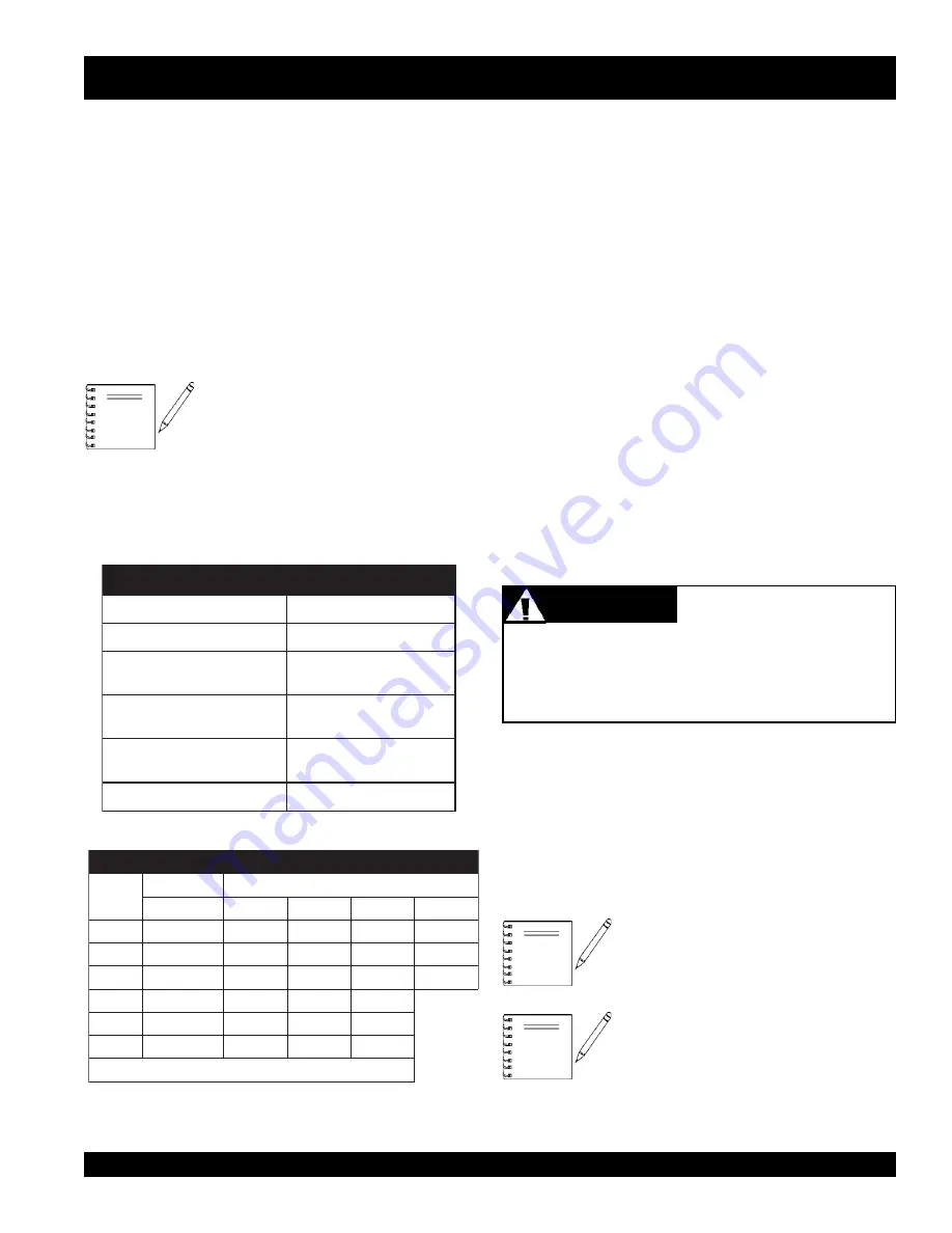
The power factor of this generator is 1.0 See Table 2 below
when connecting loads.
NOTE
GAW-135H — LOAD APPLICATION
To determine the running wattage for your load, multiply
the running wattage as indicated by steps 1, 2, and 3 below:
1.
INCANDESCENT LOADS
Lights, heaters and similar appliances.
Total the running wattage and multiply by 1.
Example:
29 light bulbs @ 100W each = 2.9 KW
use a 3 KW generator.
2.
SMALL MOTORS
Drills and other small power tools.
Total the running wattage and multiply by 2.
Example:
A 1 inch drill runs at 1 KW
use a 2 KW generator.
3.
LARGE MOTORS
Submersible pumps, table saws etc.
Total the running wattage and multiply by 3.
Example:
A conveyor belt runs at 8 KW
use a 24 KW generator.
NOTE
When using a combination of dual
receptacles, total load
should not
exceed
the rated capacity of the
generator.
Extension Cables
When electric power is to be provided to various tools or
loads at some
distance
from the generator, extension cords
are normally used.
Cables should be sized to allow for
distance in length and amperage so that the voltage drop
between the generator and point of use (load) is held to
a
minimum
. Use the cable selection chart (Table 2 ) as a
guide for selecting proper cable size.
The idle control device is operated at a
minimum load capacity of 100W. If the
load capacity is less than 100W, place
the idle control switch in the
OFF
position.
NOTE
)
n
o
i
t
a
r
e
p
O
e
s
a
h
P
e
l
g
n
i
S
,
z
H
0
6
(
n
o
i
t
c
e
l
e
S
e
l
b
a
C
.
3
e
l
b
a
T
n
i
t
n
e
r
r
u
C
s
e
r
e
p
m
A
s
t
t
a
W
n
I
d
a
o
L
h
t
g
n
e
L
e
l
b
a
C
e
l
b
a
w
o
ll
A
m
u
m
i
x
a
M
s
t
l
o
V
0
2
1
t
A
e
r
i
W
0
1
#
e
r
i
W
2
1
#
e
r
i
W
4
1
#
e
r
i
W
6
1
#
5
.
2
0
0
3
.t
f
0
0
0
1
.t
f
0
0
6
.t
f
5
7
3
.t
f
0
5
2
5
0
0
6
.t
f
0
0
5
.t
f
0
0
3
.t
f
0
0
2
.t
f
5
2
1
5
.
7
0
0
9
.t
f
0
5
3
.t
f
0
0
2
.t
f
5
2
1
.t
f
0
0
1
0
1
0
0
2
1
.t
f
0
5
2
.t
f
0
5
1
.t
f
0
0
1
5
1
0
0
8
1
.t
f
0
5
1
.t
f
0
0
1
.t
f
5
6
0
2
0
0
4
2
.t
f
5
2
1
.t
f
5
7
.t
f
0
5
.
e
g
a
t
l
o
v
w
o
l
m
o
r
f
t
l
u
s
e
r
n
a
c
e
g
a
m
a
d
t
n
e
m
p
i
u
q
E
:
N
O
I
T
U
A
C
d
a
o
L
y
B
r
o
t
c
a
F
r
e
w
o
P
.
2
e
l
b
a
T
d
a
o
L
f
O
e
p
y
T
r
o
t
c
a
F
r
e
w
o
P
s
r
o
t
o
m
n
o
it
c
u
d
n
i
e
s
a
h
p
-
e
l
g
n
i
S
5
7
.
0
-
4
.
0
t
n
e
c
s
e
d
n
a
c
n
i
,
s
r
e
t
a
e
h
c
i
r
t
c
e
l
E
s
p
m
a
l
0
.
1
y
r
u
c
e
m
,
s
p
m
a
l
t
n
e
c
s
e
r
o
u
l
F
s
p
m
a
l
9
.
0
-
4
.
0
,
s
e
c
i
v
e
d
c
i
n
o
r
t
c
e
l
E
t
n
e
m
p
i
u
q
e
n
o
it
a
c
i
n
u
m
m
o
c
0
.
1
s
l
o
o
t
r
e
w
o
p
n
o
m
m
o
C
8
.
0
Motors and motor-driven equipment draw much greater
current for starting than during operation.
Always
use an
adequate size
extension cable
which can carry the
required load.
CAUTION
CAUTION
CAUTION
CAUTION
CAUTION


