PAGE 32 — JTNSW20-24HTCSL SERIES RIDE-ON TROWEL • OPERATION MANUAL — REV. #1 (3/24/16)
MAINTENANCE
If, after making Blade Pitch adjustments the machine is
still finishing poorly, blades, trowel arms, and trowel arm
bushings may be suspect and should be looked at for
adjustment, wear, or damage. See the following sections.
Changing Blades
It is recommended that ALL the blades on the entire
machine are changed at the same time. If only one or
some of the blades are changed, the machine will not
finish concrete consistently and the machine may wobble
or bounce.
1. Place the machine on a flat, level surface. Adjust
the blade pitch control to make the blades as flat as
possible. Note the blade orientation on the trowel arm.
This is important for ride-on trowels as the two sets
of blades counter-rotate. Lift the machine up, placing
blocks under the main guard ring to support it.
2. Remove the bolts and lock washers on the trowel arm,
and then remove the blade.
3. Scrape all concrete and debris from the trowel arm.
This is important to properly seat the new blade.
4. Install the new blade, maintaining the proper orientation
for direction of rotation.
5. Reinstall the bolts and lock washers.
6. Repeat steps 2-5 for all remaining blades.
Clean-Up
Never allow concrete to harden on the power trowel.
Immediately after use wash any concrete off the trowel
with water, be careful not to spray a hot engine or muffler.
An old paint brush or broom may help loosen any concrete
that has started to harden.
Trowel Arm Adjustment Procedure
A level, clean area to test the trowel prior to and after
adjustment is essential. Any unlevel spots in the floor
or debris under the trowel blades will give an incorrect
perception of adjustment. Ideally, a 5' x 5' three-quarter
inch thick flat steel plate should be used for testing.
1. To determine which blades need adjustment, place the
trowel in the test area (three-quarter inch thick plate)
and look for the following conditions:
• Pitch the blades as flat as possible and look at the
adjustment bolts. They should all barely make contact
with the lower wear plate on the spider. If you can
see that one of them is not making contact, some
adjustment will be necessary.
• Is the machine wearing out blades unevenly (i.e. one
blade is completely worn out while the others look
new)?
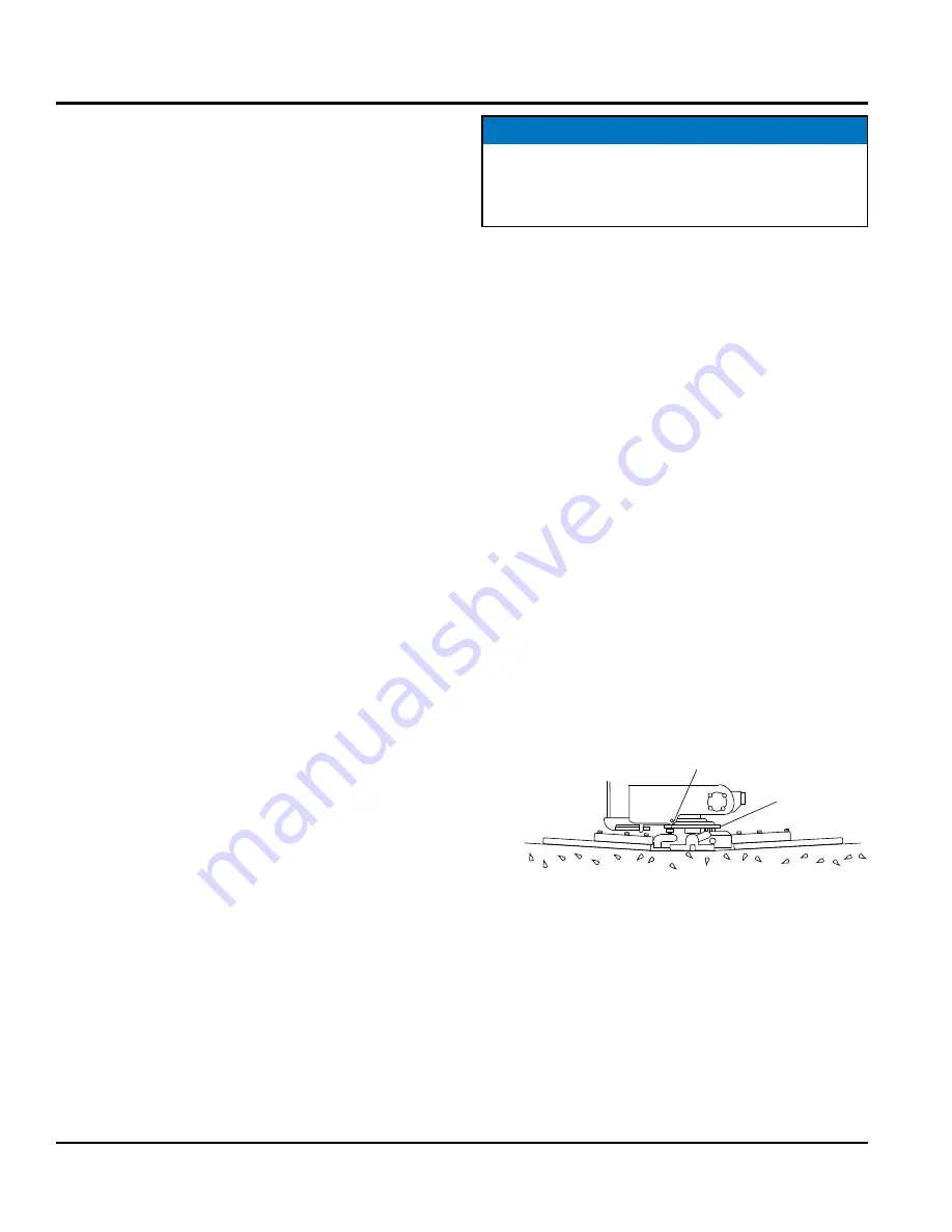
Figure 30 illustrates "worn spider bushings or bent trowel
arms". Check to see that adjustment bolt is barely touching
(0.10" max. clearance) lower wear plate. All alignment
bolts should be spaced the same distance from the lower
wear plate.
Figure 30. Worn Arm Bushings
NOTICE
The following procedure should be followed to adjust
trowel arms when it becomes apparent that the trowel
is finishing poorly or in need of routine maintenance.
SURFACE
LOWER
WEAR
PLATE
“DISHED” EFFECT ON
FINISHED CONCRETE
ADJUSTMENT
BOLT
INCORRECT
ALIGNMENT


