background image

PAGE 52 — SG1400/1600C4F STUDIO GENERATOR • OPERATION MANUAL — REV. #0 (07/22/20)

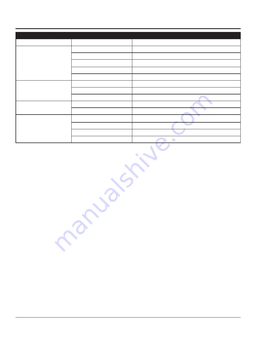
TROUBLESHOOTING (GENERATOR)

Troubleshooting (Generator)

Symptom

Possible Problem

Solution

No Voltage Output

AC Voltmeter defective?

Check output voltage using a voltmeter.

Is wiring connection loose?

Check wiring and repair.

Is voltage regulator defective?

Replace if necessary.

Defective Rotating Rectifier?

Check and replace.

Defective Exciter Field?

Check and replace.

Low Voltage Output

Is engine speed correct?

Turn engine throttle lever to “High”.

Is wiring connections loose?

Check wiring and repair.

Defective AVR?

Replace if necessary.

High Voltage Output

Is wiring connections loose?

Check wiring and repair.

Defective AVR?

Replace if necessary.

Circuit Breaker Tripped

Short Circuit in load?

Check load and repair.

Over current?

Confirm load requirements and reduce.

Defective circuit breaker?

Check and replace.

Over current Relay actuated?

Confirm load requirement and replace.

Summary of Contents for MQ POWER SG1400C4F

Page 1: ...NT AT ALL TIMES MODELS SG1400C4F SG1600C4F STUDIO GENERATOR CUMMINS QSB7 G9 DIESEL ENGINE Revision 0 07 22 20 OPERATION MANUAL To find the latest revision of this publication or associated parts manua...

Page 2: ...PAGE 2 SG1400 1600C4F STUDIO GENERATOR OPERATION MANUAL REV 0 07 22 20 PROPOSITION 65 WARNING...

Page 3: ...similar complaints it may open an investigation and if it finds that a safety defect exists in a group of vehicles it may order a recall and remedy campaign However NHTSA cannot become involved in ind...

Page 4: ...4 25 Circuit Breaker Panel 26 Digital Controller 27 Load Application Generator Output 28 Generator Outputs 29 Inspection Setup 30 34 Startup 35 37 Protective Devices 38 Maintenance 39 51 Troubleshooti...

Page 5: ...fety messages specifically address the level of exposure to the operator and are preceded by one of four words DANGER WARNING CAUTION or NOTICE SAFETY SYMBOLS DANGER Indicates a hazardous situation wh...

Page 6: ...recommended by MQ Power for this equipment Damage to the equipment and or injury to user may result ALWAYS know the location of the nearest fire extinguisher ALWAYS know the location of the nearest f...

Page 7: ...ER run engine without an air filter or with a dirty air filter Severe engine damage may occur Service air filter frequently to prevent engine malfunction NEVER tamper with the factory settings of the...

Page 8: ...ndition ALWAYS shutdown engine before transporting Make sure the hitch and coupling of the towing vehicle are rated equal to or greater than the trailer gross vehicle weight rating ALWAYS inspect the...

Page 9: ...rator Inspect for cuts in the insulation NEVER grab or touch a live power cord or cable with wet hands The possibility exists of electrical shock electrocution or death Make sure power cables are secu...

Page 10: ...le of this equipment is over remove battery and bring to appropriate facility for lead reclamation Use safety precautions when handling batteries that contain sulfuric acid When the life cycle of this...

Page 11: ...994 kg Weight Trailer Only 2 580 lbs 1 170 kg Table 2 Engine Specifications Model Cummins QSB7 G9 Emissions Tier 4 Type 4 cycle direct injection turbocharged charge air cooled EGR DOC SCR No of Cylin...

Page 12: ...14 6 J 24 610 Aluminum Wheels D 25 25 641 3 K 183 75 4 667 25 E 31 5 800 1 L 22 125 561 97 F 25 5 647 7 M 48 1 219 2 G 79 5 2 019 3 N 112 2 844 8 H 136 25 3 460 8 Figure 1 Dimensions A D B TOP VIEW SI...

Page 13: ...SG1400 1600C4F STUDIO GENERATOR OPERATION MANUAL REV 0 07 22 20 PAGE 13 NOTES...

Page 14: ...Safety Codes for proper connection based on condition of use EXAMPLEofhowtogroundtheunitifthecondition of use requires such a device The ground terminal on the generator should always be used to conn...

Page 15: ...tor They are to resist damage to the bottom of the generator and to maintain alignment CAUTION Pay close attention to ventilation when operating the generator inside tunnels and caves The engine exhau...

Page 16: ...ld is not powered This AC voltage is rectified to DC by the rotating rectifier assembly and fed directly to the main rotor field As the generator shaft continues to rotate the main rotor field induces...

Page 17: ...Interior Lighting The interior lighting system is distributed throughout the interior There are three separate lighting fixtures Two lights are in the engine compartment and one light is in the genera...

Page 18: ...ents ITEM NO DESCRIPTION 1 SCR Selective Catalytic Reduction 2 DPF Diesel Particulate Filter 3 Hydraulic Cylinders 4 Saddlebox 5 Generator 6 DEF Tank 7 Hydraulic Oil Tank 8 Hydraulic Filter 9 Charge A...

Page 19: ...24 25 27 28 26 29 GENERATOR MAJOR COMPONENTS Figure 3 Major Components Table 6 Generator Major Components ITEM NO DESCRIPTION 23 Rain Cap 24 Roof Intake Exhaust 25 Radiator Service Cap 26 DEF Tank Fi...

Page 20: ...ATOR OPERATION MANUAL REV 0 07 22 20 GENERATOR OPTIONS Table 7 Generator Options ITEM NO DESCRIPTION 1 Exterior LED Lights 2 Block Heater 3 Battery Charger 4 Fire Extinguisher 5 Transformer Table 8 1...

Page 21: ...IC ENGINE COMPONENTS Table 9 Basic Engine Components ITEM NO DESCRIPTION 1 Alternator 2 Oil Filter 3 Starter Solenoid 4 Turbocharger 5 Oil Filler Port 6 Fuel Filter 7 Oil Dipstick 8 V Belt 9 Water Pum...

Page 22: ...ing is 3 500 lbs tire 7 ReflectiveTape Provides high visibility when towing in dark areas 8 Brake Turn Lights DOT approved tail stop and turn signal lamps 9 Bumper Guard Protects trailer frame when co...

Page 23: ...15 minutes The lights will automatically shut off when the timer reaches zero 8 Light Switch In the up position turns on exterior lights In the down position turns on panel lighting In the center posi...

Page 24: ...ARALLELING CABLE IN DO NOT CONNECT OR DISCONNECT CABLES WHEN BUS HOT LIGHT IS ILLUMINATED CAUTION 120 VAC 100 AMP N N L1 L1 L2 L2 L3 L3 125 250V 50 AMP 120 VAC 15 AMP GENERATOR TEST POINTS G N L1 L2 L...

Page 25: ...connecting and disconnecting power cables from these camlok receptacles The possibility exists of electrocution shock or even death if cables are connected or unplugged when the bus hot indicator lam...

Page 26: ...g the trip point on the electric trip unit be careful not to set the trip point too high Setting the trip point too high may cause the main breaker not to trip This condition could cause serious damag...

Page 27: ...9 GCB Generator Circuit Breaker CONTROL Button Press button to close open GCB 10 MCB CONTROL Button Not functional in this application CONTROL BUTTONS 11 START Button Press button to go idle mode abou...

Page 28: ...Factor By Load Type of Load Power Factor Single phase induction motors 0 4 0 75 Electric heaters incandescent lamps 1 0 Fluorescent lamps mercury lamps 0 4 0 9 Electronic devices communication equipme...

Page 29: ...120 240 Volt 3 120 208 Volt N A 2 Position Switch 3 120 208 Volt 3 277 480 Volt N A 120 208 3 120 240 1 277 480 3 120 208 3 277 480 3 120 208 3 120 240 1 Generator Amperage Table 14 shows the maximum...

Page 30: ...Service Classification CC SD API Service Classification CC SE API Service Classification CC SF Table 15 Recommended Motor Oil FUEL CHECK RefillingtheFuelSystem TrailerMountedGenerators This generator...

Page 31: ...k Figure 14 Figure 14 Fueling the Generator DIESEL FUEL UNLEVEL GROUND LEVEL GROUND NOTICE ONLY use 2 diesel fuel when refueling DIESEL FUEL 3 Monitor the fuel gauge while filling fuel tank Stop filli...

Page 32: ...FUEL IN DEF Refueling Diesel exhaust fluid is an aqueous solution made with 32 5 high puirty urea carbamide and 67 5 deionized water DEF is used as a consumable in selective catalytic reduction SCR i...

Page 33: ...erve Tank 6 quarts 6 6 liters Table 17 Anti Freeze OperatingTemperatures Vol Anti Freeze Freezing Point Boiling Point C F C F 50 37 34 108 226 NOTICE When the antifreeze is mixed with water the antifr...

Page 34: ...ive terminal LAST NEGATIVE BLACK POSITIVE RED When connecting the battery do the following 1 Place a small amount of battery terminal treatment compound around both battery terminals This will ensure...

Page 35: ...rconnect the units Interconnect the output buses with suitable power cables to carry full load capacity Special male to male Camlok cables will be needed For 480V mode it is recommended that one 4 0 c...

Page 36: ...N START BUTTON NOTICE If START button is not pressed again the engine will remain in idle mode for about an hour then will go to full speed 7 Press the GCB control button on the controller Figure 27 t...

Page 37: ...Press the GCB control button on the controller Figure 30 to open circuit breaker 2 Let the engine cool by running it at full speed for 3 5 minutes with no load applied 3 Press the STOP button Figure 3...

Page 38: ...oller will display the cause of the fault Before inspecting or troubleshooting the generator press the OFF button on the Digital Controller Place the main circuit breaker in the OFF position and allow...

Page 39: ...X Engine Coolant Antifreeze Check X Fuel Filter Spin On Type Replace X Lubricating Oil and Filters Change X Radiator Pressure Cap Check X Cooling Fan Belt Tensioner Check X Fan Hub Belt Driven Check X...

Page 40: ...L INSPECTION Prior to each use the generator should be cleaned and inspected for deficiencies Check for loose missing or damaged nuts bolts and other fasteners Also check for fuel oil and coolant leak...

Page 41: ...case body as referenced in Figure 36 NOTICE DO NOT use excessive air pressure or the paper air filter element will be damaged and will need to be replaced If air filters are excessively dirty oily Re...

Page 42: ...ting conditions NOTICE If the engine is operating in very dusty or dry grass conditions a clogged air cleaner will result This can lead to a loss of power excessive carbon buildup in the combustion ch...

Page 43: ...nside of the bowl with a clean cloth to remove any foregn matter or debris that may have accumulated 4 Visually inspect the fuel strainer screen If screen is clogged with debris or foreighn matter cle...

Page 44: ...h the separator for the sediment and foreign matter to drain into Figure 42B Figure 42 Fuel Water Separator Draining 4 When all fluid and foreign matter has been drained from the separator turn the dr...

Page 45: ...sembling the fuel system bleed the system For more detailed information for more detailed information refer to the Cummins Owner s Manual Bleeding the Fuel System ALLEN WRENCH AIR BLEEDER SCREW FUEL W...

Page 46: ...with oil Replace the rubber suspension if necessary Fuel Hoses inspect nylon and rubber hoses for signs of wear deterioration and hardening FuelTank Lining inspect the fuel tank lining for signs of ex...

Page 47: ...0 hours 1 Using an oil filter wrench Figure 51A remove engine oil filter 2 Clean the area around the lubricating oil filter head Figure 51 Engine Oil Filter Removal 3 Coat the rubber seal gasket on th...

Page 48: ...gure 53A remove hydraulic oil filter 3 Clean the area around the hydraulic oil filter head and wipe up any fluid that might have spilled 4 Coat the rubber seal gasket on the hydraulic oil filter Figur...

Page 49: ...NTENANCE 3 After engine coolant has been completely drained reinstall drain plug and tighten securely FLUSHING RADIATOR 1 Remove radiator cap 2 Open coolant drain plug located at the base of the skid...

Page 50: ...remove the radiator cap until the unit has completely cooled The possibility of hot coolant exists which can cause severe burns DEFTANK SUPPLY MODULE FILTER Replace DEF Supply Module Filter every 4500...

Page 51: ...system The chemical reaction is known as reduction where the DEF is the reducing agent that reacts with NOx to convert the pollutants into nitrogen water and tiny amounts of CO2 The DEF can be rapidly...

Page 52: ...ifier Check and replace Defective Exciter Field Check and replace Low Voltage Output Is engine speed correct Turn engine throttle lever to High Is wiring connections loose Check wiring and repair Defe...

Page 53: ...ngine oil too thick Refill engine crankcase with correct type of oil for winter environment Defective battery Replace battery Engine fires but stops soon as starter is switched off Fuel filter blocked...

Page 54: ...ntroller configuration upgrade is necessary Controller was not detected Error Controller is not connected or communication via RS485 is interrupted Communication is lost or RS485 line A and B are swap...

Page 55: ...I1 J2 A3 G2 B3 O2 H1 G M D1 C1 B1 A1 E1 Z X Y O F H2 A2 G1 N A E U R F2 E2 D2 N2 M2 L2 Q1 G1 N1 M1 W I2 I2 Z2 B2 A3 G2 O2 S K2 J2 B3 EE56444 EE56762 J H G3 J3 H3 B C C2 W2 C3 Q V2 F3 X2 Y2 M3 N3 G3 K...

Page 56: ...OSING CONNECTOR GRY RED WHT DEF SUCTION LINE HEATER CONNECTOR DEF SUPPLY MODULE RETURN 30 AMP CB10 GRN RED MODULE CONNECTOR 32 SENSOR 16 DEF PUMP MOTOR SUPPLY DEF PUMP MOTOR GND 303 B A C DEF SUPPLY H...

Page 57: ...AWG PURPLE 12 AWG PURPLE BLU GRY ATM10 12 AWG WHITE 12 AWG GREEN 12 AWG WHITE 12 AWG GREEN BLK ORG RED ORG BLU ORG BLK ORG RED ORG GRY ORG BLK ORG RED ORG YEL ORG AC17 AC20 AC21 AC22 AC23 GREEN CONTR...

Page 58: ...501 140 14 14 C C 5 C 14 14 1 0 A1 A2 12 1 2 1 0 54 55 10 5 14 04 05 A A 1 14 2 A C 25 52 51 50 1 14 14 54 5 A C 40 5 5 5 A 2 4 5 12 1 2 4 1 2 1 4 2 4 1 2 1 4 2 22 1 2 1 2 1 2 1 4 10 11 1 2 4 14 14 1...

Page 59: ...AC21 AC22 44 45 50 51 1 50 AMP 120 240 VAC 1 50 AMP 50 AMP 120 240 VAC 1 50 AMP 525 524 522 520 521 510 515 514 512 511 505 504 502 500 501 0V 0V 120V 1 4 12 AC4 AC1 AC2 4 AC2 AC1 A L2 M2 N2 E2 F2 D2...

Page 60: ...2 500 501 140 14 14 C C 5 C 14 14 1 0 A1 A2 12 1 2 1 0 54 55 10 5 14 04 05 A A 1 14 2 A C 25 52 51 50 1 14 14 54 5 A C 40 5 5 5 A 2 4 5 12 1 2 4 1 2 1 4 2 4 1 2 1 4 2 22 1 2 1 2 1 2 1 4 10 11 1 2 4 14...

Page 61: ...12 5 1 AC20 AC21 AC22 50 51 525 524 522 520 521 510 515 514 512 511 505 504 502 500 501 120VAC 15A 15A 120VAC 15A 120VAC 5 A2 A1 1 5 2 4 15 AMP 15 AMP 120VAC 15A 120VAC 15A L2 M2 N2 E2 F2 D2 N B2 G2 Y...

Page 62: ...2 500 501 140 14 14 C C 5 C 14 14 1 0 A1 A2 12 1 2 1 0 54 55 10 5 14 04 05 A A 1 14 2 A C 25 52 51 50 1 14 14 54 5 A C 40 5 5 5 A 2 4 5 12 1 2 4 1 2 1 4 2 4 1 2 1 4 2 22 1 2 1 2 1 2 1 4 10 11 1 2 4 14...

Page 63: ...20 VAC 2 4 15 AMP 15 AMP 120VAC 15A 120VAC 15A AC20 AC21 AC22 50 51 A1 5 525 524 522 520 521 510 515 514 512 511 505 504 502 500 501 120VAC 15A 15A 120VAC 15A 120VAC L2 M2 N2 E2 F2 D2 N B2 G2 Y1 O Z1...

Page 64: ...405 404 401 400 1 0 521 511 501 140 14 14 C C 5 C 14 14 1 0 A1 A2 12 1 2 1 0 54 55 10 5 14 04 05 A A 1 14 2 A C 25 52 51 50 1 14 14 54 5 A C 40 5 5 5 A 2 4 5 12 1 2 4 1 2 1 4 2 4 1 2 1 4 2 22 1 2 1 2...

Page 65: ...0V 0V 120V 1 4 12 AC4 AC1 AC2 4 AC2 AC1 A 12 14 1 10 4 2 1 5 1 1 5 2 4 15 AMP 15 AMP 120VAC 15A 120VAC 15A 100 AMP 100 AMP 521 511 501 50 AMP 120 240 VAC 1 50 AMP 50 AMP 120 240 VAC 1 50 AMP L2 M2 N2...

Page 66: ...00 501 140 14 14 14 C C 5 C 14 14 1 0 A1 A2 12 1 2 1 0 54 55 10 5 14 04 05 A A 1 14 2 A C 25 52 51 50 1 14 14 54 5 A C 40 5 5 5 A 2 4 5 12 1 2 4 1 2 1 4 2 4 1 2 1 4 2 22 1 2 1 2 1 2 1 4 10 11 1 2 4 14...

Page 67: ...AMP 14 1 4 42 22 12 100 AMP 100 AMP 4 12 12 5 1 1 5 120 VAC 2 4 15 AMP 15 AMP 120VAC 15A 120VAC 15A AC20 AC21 AC22 50 51 5 A2 A1 2 A V A C 120VAC 15A 15A 120VAC 15A 120VAC L2 M2 N2 E2 F2 D2 N B2 G2 Y...

Page 68: ...PAGE 68 SG1400 1600C4F STUDIO GENERATOR OPERATION MANUAL REV 0 07 22 20 HYDRAULIC DIAGRAM LOCATOR R Q C P E A I F D B H...

Page 69: ...SG1400 1600C4F STUDIO GENERATOR OPERATION MANUAL REV 0 07 22 20 PAGE 69 HYDRAULIC DIAGRAM LOCATOR L K O J G N M...

Page 70: ...E 70 SG1400 1600C4F STUDIO GENERATOR OPERATION MANUAL REV 0 07 22 20 MHYDRAULIC DIAGRAM O DIRECTIONAL CONTROL VALVE DIRECTIONAL CONTROL VALVE EXHAUST CYLINDERS 1 4 NPT G L F J K B A I D M H P O Q C E...

Page 71: ...SG1400 1600C4F STUDIO GENERATOR OPERATION MANUAL REV 0 07 22 20 PAGE 71 NOTES...

Page 72: ...ct at the time of approval for printing Illustrations descriptions references and technical data contained in this manual are for guidance only and may not be considered as binding Multiquip Inc reser...

Reviews: