background image

DCA-150SSJU3— OPERATION AND PARTS MANUAL — REV. #0  (11/14/07) — PAGE 33

1

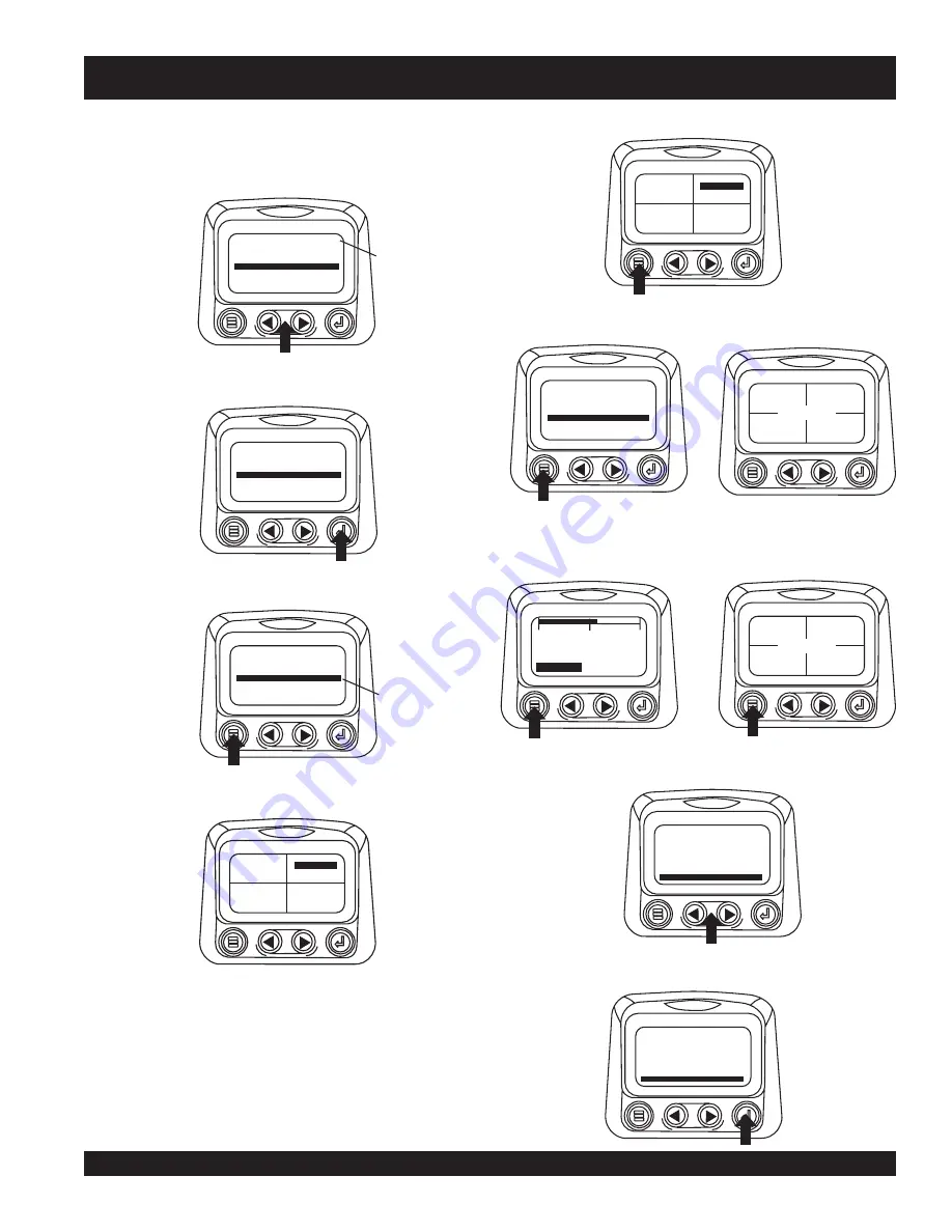
9.

The parameter that is highlighted is the selected
parameter for the screen. Use the “Arrow Buttons” to
highlight the new parameter to be placed in the quadrant
selected in the previous screen.

10. Touch the “Enter Button” to change the selected

parameter in the quadrant to the new parameter.

11. Use the “Menu Button” to return to the “4-Up Custom

Setup” screen.

12. The parameter in the selected quadrant has changed

to the parameter selected in the previous screen.

13. Repeat the parameter selection process until all spaces

are filled.

14. Touch the “Menu Button” to return to the main menu.

15. Touch the “Menu Button” to exit the Main menu and

return to the engine parameter display.

Utilities

 (information and troubleshooting)

1. Starting at the single or four engine parameter display,

touch the “Menu Button”.

2. The main menu will be displayed. Use the “Arrow Buttons”

to scroll through the menu until the “Utilities” is
highlighted.

3. Once the “Utilities” menu item has been highlighted, touch

the “Enter Button” to activate the “Utilities” functions.

ENGINE SPEED

ENGINE COOLANT TEMPERATURE
BATTERY POTENTIAL

ENGINE OIL PRESSURE

ENGINE HOURS

ENGINE OIL TEMPERATURE

3

1

4

2

The number to the right
of the parameter indicates
the quadrant in which it
is displayed.
1= Upper Left Quadrant
2 = Lower Left Quadrant
3 = Upper Right Quadrant
4 = Lower Right Quadrant

ENGINE SPEED

ENGINE COOLANT TEMPERATURE
BATTERY POTENTIAL

ENGINE OIL PRESSURE

ENGINE HOURS

ENGINE OIL TEMPERATURE

3

1
2

4

ENGINE SPEED

ENGINE COOLANT TEMPERATURE
BATTERY POTENTIAL

ENGINE OIL PRESSURE

ENGINE HOURS

ENGINE OIL TEMPERATURE

3

1

4

2

Note the number to
the right of the selected
parameter indicating that the
parameter is now assigned
to that display location

125°F

COOL TEMP

143°F

OIL TEMP

57 PSI

1000 RPM

ENG RPM

OIL PRES

125°F

COOL TEMP

143°F

OIL TEMP

57 PSI

1000 RPM

ENG RPM

OIL PRES

GO TO 1-UP DISPLAY
STORED CODES
ENGINE CONFG

ADJUST BACKLIGHT

SETUP 1-UP DISPLAY

SELECT UNITS

SETUP-4-UP DISPLAY

125°F

COOL TEMP

143°F

OIL TEMP

57 PSI

1000 RPM

ENG RPM

OIL PRES

COOL

1800 RPM

0

1500

3000

TEMP

ENG RPM

125°F

COOL TEMP

143°F

OIL TEMP

57 PSI

1000 RPM

ENG RPM

OIL PRES

ENGINE CONF

SETUP-4-UP DISPLAY
SELECT UNITS

STORED CODES

G

SETUP 1-UP DISPLAY

ADJUST BACKLIGHT

UTILITIES

ENGINE CONF

SETUP-4-UP DISPLAY
SELECT UNITS

STORED CODES

G

SETUP 1-UP DISPLAY

ADJUST BACKLIGHT

UTILITIES

DCA-150SSJU3 — DIAGNOSTIC DISPLAY

Summary of Contents for Power WHISPERWATT DCA-150SSJU3

Page 1: ...S AND OPERATION MANUAL OPERATION AND PARTS MANUAL Revision 0 11 14 07 THIS MANUAL MUST ACCOMPANY THE EQUIPMENT AT ALLTIMES WHISPERWATTTM SERIES MODEL DCA 150SSJU3 60 Hz GENERATOR PARTS LIST NO M387030...

Page 2: ...PAGE 2 DCA 150SSJU3 OPERATION AND PARTS MANUAL REV 0 11 14 07...

Page 3: ...ustrations are basedontheDCA 150SSJU3 WHISPERWATTACGenerator MultiquipInc reservestherighttodiscontinueorchangespecifications design or the information published in this publication at any time withou...

Page 4: ...utputTerminal Panel Familiarization 40 42 Load Application 43 Generator Outputs 44 GaugeReading 45 OutputTerminal Panel Connections 46 47 Setup 48 51 Generator Start up Procedure Manual 52 54 Generato...

Page 5: ...b parts order system or by fax qualify for the following extra discounts Ordered Standard Stock orders via orders 750 list and above Fax 3 10 Web 5 10 Special freight allowances when you order 10 or m...

Page 6: ...1 t u p t u O 2 x W K 4 2 W K 8 4 s n o i t a c i f i c e p S e n i g n E l e d o M 5 8 2 F H 8 6 0 6 E R E E D N H O J e p y T d e g r a h c o b r u t n o i t c e j n i t c e r i d d e l o o c r e t...

Page 7: ...E M I D 3 E L B A T e c n e r e f e R r e t t e L m m t f n o i s n e m i D r e t t e L e c n e r e f e R m m t f n o i s n e m i D A m m 0 9 8 n i 3 0 5 3 F m m 0 0 2 3 n i 8 9 5 2 1 B m m 0 9 8 n i...

Page 8: ...r SERIOUSLY injured if you do not follow directions You COULD be KILLED or SERIOUSLY injured if you do not follow directions You CAN be injured if you do not follow directions Gasoline engine exhaust...

Page 9: ...environment Thisgenerator otherproperty or the surrounding environment could be damaged if you do not follow instructions NOTE NEVER tamper with the factory settings of the engine governor or setting...

Page 10: ...touch the hot exhaust manifold muffler or cylinder Allow these parts to cool before servicing engine or generator HighTemperatures Allowtheengine to cool before performing service and maintenance fun...

Page 11: ...equipment it is important to provide a good EARTH ground Article 250 Grounding of the National Electrical Code NEC providesguidelinesforpropergroundingandspecifies that the cable ground shall be conne...

Page 12: ...ush out of the radiator causing severe scalding to any persons in the general area of the generator Coolant Drain Plug Removing the coolant drain plug while the engine is hot will result in hot coolan...

Page 13: ...ss depending on type of terrain Place support blocks underneath the trailer s bumper to prevent tipping while parked Avoid sharp turns to prevent rolling DO NOT transport generator with fuel in tank T...

Page 14: ...ls Figures 2 3 These decals are provided for operator safety and maintenance information The illustration below and on the preceding page show the decals as they appear on the machine Should any of th...

Page 15: ...DCA 150SSJU3 OPERATION AND PARTS MANUAL REV 0 11 14 07 PAGE 15 1 DCA 150SSJU3 GENERATOR DECALS Figure 3 Generator Decals Cont inued...

Page 16: ...PAGE 16 DCA 150SSJU3 OPERATION AND PARTS MANUAL REV 0 11 14 07 Figure 4 Typical Generator Grounding Application DCA 150SSJU3 INSTALLATION...

Page 17: ...m2 or larger b Aluminum 8 AWG 8 4 mm2 or larger 2 When grounding the generator Figure 4 connect the ground cable between the lock washer and the nut on the generator and tighten the nut fully Connect...

Page 18: ...rovides virtually unlimited excitation current offering maximum motor starting capabilities The excitation does not have a fixed ceiling and responds according the demands of the required load Engine...

Page 19: ...i m r e T t u p t u O 2 y l b m e s s A s e l c a t p e c e R t u p t u O 3 y l b m e s s A r e t l i F r i A 4 y l b m e s s A r e l f f u M 5 y l b m e s s A k n a T l e u F 6 y l b m e s s A e n i...

Page 20: ...controls and functions of the Diagnostic Display Panel Figure 6 1 Menu Button Press this button to enter or exit menu screens 2 Left Arrow Button Press this button to scroll through thescreeneithermo...

Page 21: ...played Touchingthe ArrowButtons willscrollthrough the menu selection 3 Touching the right arrow button will scroll down to reveal the last items of Main Menu screen highlighting the next item down 4 T...

Page 22: ...L PRES GO TO 1 UP DISPLAY G ADJUST BACKLIGHT ENGINE CONF SETUP 1 UP DISPLAY SETUP 4 UP DISPLAY SELECT UNITS STORED CODES 4 If the word MORE appears above the Arrow Buttons there are more stored fault...

Page 23: ...played Touchingthe ArrowButtons willscrollthrough the menu selection 3 Touching the right arrow button will scroll down to reveal the last items of Main Menu screen highlighting the next item down 4 T...

Page 24: ...L PRES GO TO 1 UP DISPLAY G ADJUST BACKLIGHT ENGINE CONF SETUP 1 UP DISPLAY SETUP 4 UP DISPLAY SELECT UNITS STORED CODES 4 If the word MORE appears above the Arrow Buttons there are more stored fault...

Page 25: ...via a daisy chained RS 485 port If at any time during system initialization or normal operation an auxiliary gage should fail the single orfourparameterscreenwillbereplacedwiththe MLink Gage Fault mes...

Page 26: ...OIL PRES 98 14 2 57 PSI 1000 RPM LOAD RPM BATT VOLT ENG RPM OIL PRES SPN110 FMI10 HIGH COOLANT TEMP WARNING 1 of x MORE HIDE SPN110 FMI10 HIGH COOLANT TEMP 1 of x MORE HIDE 4 To acknowledge and Hide...

Page 27: ...OOL 1800 RPM 0 1500 3000 TEMP ENG RPM 98 14 2 57 PSI 1000 RPM LOAD RPM BATT VOLT ENG RPM OIL PRES 5 Touching the Enter Button once again will hide the faultandreturnthescreentothesingleorfourparameter...

Page 28: ...nter Button to activate the Adjust Contrast function 4 Use the Arrow Buttons to select the desired contrast intensity 5 Touching the Menu Button will take you back through the menus GO TO 1 UP DISPLAY...

Page 29: ...lay touch the Menu Button COOL 1800 RPM 0 1500 3000 TEMP ENG RPM 98 14 2 57 PSI 1000 RPM LOAD RPM BATT VOLT ENG RPM OIL PRES GO TO 1 UP DISPLAY STORED CODES G ADJUST BACKLIGHT ENGINE CONF SETUP 1 UP D...

Page 30: ...tton to activate the Use Defaults function GO TO 1 UP DISPLAY STORED CODES G ADJUST BACKLIGHT ENGINE CONF SETUP 4 UP DISPLAY SELECT UNITS SETUP 1 UP DISPLAY USE DEFAULTS CUSTOM SETUP AUTOMATIC SCAN OF...

Page 31: ...an function on 17 Touchingthe EnterButton againtogglesthe Automatic Scan function off 18 Oncethe UseDefaults CustomSetup and Automatic Scan functions have been set touch the Menu Button to return to t...

Page 32: ...PLAY STORED CODES ENGINE CONFG ADJUST BACKLIGHT SETUP 1 UP DISPLAY SELECT UNITS SETUP 4 UP DISPLAY GO TO 1 UP DISPLAY STORED CODES ENGINE CONFG ADJUST BACKLIGHT SETUP 1 UP DISPLAY SELECT UNITS SETUP 4...

Page 33: ...COOLANT TEMPERATURE BATTERY POTENTIAL ENGINE OIL PRESSURE ENGINE HOURS ENGINE OIL TEMPERATURE 3 1 4 2 The number to the right of the parameter indicates the quadrant in which it is displayed 1 Upper...

Page 34: ...version currently in the diagnostic display 9 Touch Menu to return to Utilities Highlight Fault Conversion using the Arrows Touch Select to enter the Fault conversion menu 10 Use the Arrows to scroll...

Page 35: ...lave 5 Use the Arrows to scroll to the Serial Port menu to highlight it then touch Enter 6 Use the Arrow button to scroll to each selection to configure the MODBUS values for your application 7 When f...

Page 36: ...is not supported DATAERROR Diagnostic Display has received an error message from the ECU for the displayed message EMPTY No parameter selected for this 4 UP quadrant WAITTO START PREHEATING This is a...

Page 37: ...oltmeter Change Over Switch This switch allows the AC voltmeter to indicate phase to phase voltage between any two phases of the output terminals or to be switched off 7 Main Circuit Breaker This thre...

Page 38: ...arting the generator the oil pressure may read a little higher but after the engine warms up the oil pressure should return to the correct pressure range 4 Water Temperature Gauge During normal operat...

Page 39: ...using variable resistive values from the oil pressure sending unit This is considered a major fault C High Coolant Temperature Indicates the engine temperature has exceeded 239 F The engine temperatu...

Page 40: ...0V GFCI receptacles 20 amp Two 2 GFCI Circuit Breakers 20 amps Five 5 Output Terminal Lugs U V W O Ground OutputTerminal Panel TheOutputTerminalPanel Figure9 shownbelowislocated ontheright handside le...

Page 41: ...current on all three receptacles is dependent on the load requirements of the OutputTerminal Lugs Turn the voltage regulator control knob Figure 12 on the control panel to obtain the desired voltage...

Page 42: ...a 3 pole 400A main circuit breaker is provided Make sure to switch ALL circuit breakers to the OFF position prior to starting the engine DCA 150SSJU3 OUTPUT TERMINAL PANEL FAMILIARIZATION Over Curren...

Page 43: ...ting current capacity NOTE WATTS VOLTAGE x AMPERAGE Three Phase Load When calculating the power requirements for 3 phase power use the following equation NOTE An inadequate size connecting cable which...

Page 44: ...d for ease of voltage selection CAUTION CHANGINGVOLTAGES NEVER attempt to place jumper plates on the voltage change over board while the generator is in operation There exist the possibility of electr...

Page 45: ...19 to the U or W position Use the AC voltmeter or AC ammeter Figures 18 and 20 to read the output on the selected leg of the UVWO terminals Figure 17 ACVoltmeter Change Over Switch Figure 18 ACVoltmet...

Page 46: ...OutputTerminal Lugs 3 240 139V Connections 2 Connect the load wires to the OutputTerminal Lugs as shown in Figure 23 3 Turn the voltage regulator knob Figure 23 clockwise to increase voltage output tu...

Page 47: ...gs as shown in Figure 28 3 Turn the voltage regulator knob Figure 24 clockwise to increase voltage output turn counterclockwise to decrease voltage output 1 240V 120V OutputTerminal LugVoltages 1 Plac...

Page 48: ...e OFF position prior to starting the engine Lubrication Oil Fill the engine crankcase with lubricating oil through the filler hole but DO NOT overfill Make sure the generator is level and verify that...

Page 49: ...Figure 34 Figure 34 Full Fuel Tank Figure 35 Fuel Expansion 3 Open cabinet doors on the right side of the generator fromgeneratorcontrolpanelposition Removefuelcap and fill tank Figure 33 Figure 33 F...

Page 50: ...ging of the battery Inspect the fan belt for damage and wear and adjust it in accordance with the John Deere Engine Owner s Manual The fan belt tension is proper if the fan belt bends 10 to 15 mm Figu...

Page 51: ...wear and tightness Tighten all hose clamps and check hoses for leaks If any hose fuel or oil lines are defective replace them immediately If the battery cable is connected incorrectly electricaldamage...

Page 52: ...cover Remove this cover to gain access to the terminals Tighten terminal nuts securely to prevent load wires from slipping out 6 Close all engine enclosure doors Figure 40 CAUTION LETHAL EXHAUST HAZA...

Page 53: ...on Figure 43 Active Fault Code Message 6 In a situation where several engine problems occur simultaneously the word MORE appears above the arrow buttons indicating that there are more fault codes that...

Page 54: ...s the anticipated amount of current with respect to the load The ammeter will only display a current reading if a load is in use Figure 54 Ammeter Load 20 The generator will run until manually stopped...

Page 55: ...any maintenance when the generator is in the auto mode WARNING AUTO MODE MAINTENANCE DCA 150SSJU3 GENERATORSTART UPPROCEDURE AUTOMODE WhentheMPECControlSwitch is placed in the AUTO position the engin...

Page 56: ...150SSJU3 GENERATOR SHUT DOWN PROCEDURES 3 Let the engine cool by running it at low speed for 3 5 minutes with no load applied 4 Place the MPEC Control Switch Figure 57 to the OFF RESET position Figure...

Page 57: ...vice After changing the air element press the dust indicator button to reset the indicator E C N A N E T N I A M N O I T C E P S N I 4 1 E L B A T s r H 0 1 Y L I A D s r H 0 5 2 s r H 0 0 5 s r H 0 0...

Page 58: ...fter disassembling the fuel system bleed the system according to the following procedure See the John Deere Engine Manual for details To restart after running out of fuel turn the switch to the ON pos...

Page 59: ...ceptacles will ONLY function when commercial power has been supplied to them Figure 58 To apply commercial power to these receptacles a power cord of adequate size will be required SeeTable 6 When usi...

Page 60: ...with the trailer so the brake lights and turn signals can be connected to the towing vehicle 16 Application Indicates which units can be employed on a particular trailer Trailer Maintenance This secti...

Page 61: ...csurgebrakingrequirestheinstallationofanactuator at the tongue of the trailer Remember the surge or push of the trailer toward the tow vehicle automatically synchronizes the trailer brakes with the to...

Page 62: ...loosening of fasteners Replace all damaged parts suspension immediately Torqued suspension components as detailed in Table 17 Figure 60 Major Suspension Components DCA 150SSJU3 MAINTENANCE TRAILER DO...

Page 63: ...of the wheels is as follows 1 Start all wheel lug nuts by hand 2 Torque all lug nuts in sequence see Figure 61 DO NOT torque the wheel lug nuts all the way down Tighten each lug nut in 3 separate pass...

Page 64: ...PAGE 64 DCA 150SSJU3 OPERATION AND PARTS MANUAL REV 0 11 14 07 DCA 150SSJU3 TRAILERWIRING DIAGRAM Figure 62 Trailer Towing Vehicle Wiring Diagram...

Page 65: ...DCA 150SSJU3 OPERATION AND PARTS MANUAL REV 0 11 14 07 PAGE 65 1 DCA 150SSJU3 GENERATORWIRING DIAGRAM Figure 63 GeneratorWiring Diagram...

Page 66: ...PAGE 66 DCA 150SSJU3 OPERATION AND PARTS MANUAL REV 0 11 14 07 DCA 150SSJU3 ENGINEWIRINGDIAGRAM Figure 64 Engine Wiring Diagram...

Page 67: ...t a t o R e v i t c e f e D e c a l p e r d n a k c e h C d l e i F r e t i c x E e v i t c e f e D 1 N C n o K J s s o r c a s m h o 3 7 1 r o f k c e h C t u p t u O e g a t l o V w o L t c e r r o...

Page 68: ...c h g i H n o s i t h g i l t c e r r o c n i n o i s n e t t l e b n a F t l e b n a f e c a l p e r n e t h g i T r o t a i d a r h g u o r h t n o i t a l u c r i c t o n s i w o l f r i A l l i r...

Page 69: ...DCA 150SSJU3 OPERATION AND PARTS MANUAL REV 0 11 14 07 PAGE 69 1 NOTE PAGE...

Page 70: ...f available items Examples include battery cables shims and certain washers and nuts Not Sold Separately Indicates that an item cannot be purchased as a separate item and is either part of an assembly...

Page 71: ...1 M3310501403 HOSE RADIATOR UPPER 1 M3310501503 HOSE RADIATOR LOWER 1 0602011062 RADIATOR CAP 1 0605505070 FUEL CAP 1 0602015231 V BELT FAN 1 0602122272 UNIT OIL PRESSURE 1 0602123263 UNIT WATER TEMP...

Page 72: ...PAGE 72 DCA 150SSJU3 OPERATION AND PARTS MANUAL REV 0 11 14 07 DCA 150SSJU3 GENERATOR ASSY GENERATOR ASSY...

Page 73: ...12 BEARING 1 2 C0130000603 STARTOR ASSY 1 3 0845041804 GROMMET 2 4 8131315202 END BRACKET 1 5 8101350013 FIELD ASSY EXCITER 1 6 0012110060 HEX HEAD BOLT 4 7 0042610000 SPRINGWASHER 4 8 0041210000 PLAI...

Page 74: ...PAGE 74 DCA 150SSJU3 OPERATION AND PARTS MANUAL REV 0 11 14 07 DCA 150SSJU3 CONTROL BOX ASSY CONTROL BOX ASSY...

Page 75: ...GNOSTIC GAUGE 1 14 0016908020 HEX HEAD BOLT 2 15 0602120690 POWER VIEW 1 RE521565 16 0601831330 DIAGNOSTIC SWITCH 1 17 0601813977 RECEPTACLE 1 17A 0601812891 DUST CAP 1 17B 0601812890 STRAIN RELIEF 1...

Page 76: ...PAGE 76 DCA 150SSJU3 OPERATION AND PARTS MANUAL REV 0 11 14 07 CONTROL BOX ASSY CONT DCA 150SSJU3 CONTROL BOX ASSY CONT...

Page 77: ...AC VOLTMETER O 600V 1 48 0601801041 CHANGE OVER SWITCH VOLTMETER 1 49 0601840073 RHEOSTAT VR 2W 1K OHM 1 50 0601840121 KNOB 1 51 ECU9988NJD CONTROLLER ECU 1 REPLACES P N 0602202593 52 0021004040 MACHI...

Page 78: ...PAGE 78 DCA 150SSJU3 OPERATION AND PARTS MANUAL REV 0 11 14 07 DCA 150SSJU3 ENGINE AND RADIATOR ASSY ENGINE AND RADIATOR ASSY...

Page 79: ...GWASHER 2 12 M3923200104 RADIATOR 1 12 1 0602011062 CAP 1 12 2 M4493601304 RUBBER SEAL 2 13 M9200100904 PLUG 1 14 0150000016 O RING 1 15 0016908020 HEX HEAD BOLT 16 16 M3310501403 RADIATOR HOSE UPPER...

Page 80: ...PAGE 80 DCA 150SSJU3 OPERATION AND PARTS MANUAL REV 0 11 14 07 DCA 150SSJU3 ENGINE AND RADIATOR ASSY CONT ENGINE AND RADIATOR ASSY CONT...

Page 81: ...RESERVE TANK 1 47 0602010900 CAP RESERVE TANK 1 48 M3316100504 BRACKET RESERVE TANK 1 49 0016908020 HEX HEAD BOLT 2 50 0199901050 HOSE 1 51 0193601400 HOSE 1 52 0193600650 HOSE 1 53 0605515106 HOSE BA...

Page 82: ...OUTPUTTERMINAL ASSY OUTPUT TERMINAL ASSY THE SERIAL NUMBER MAY BE REQUIRED ADD THE FOLLOWING DIGITS AFTER THE PART NUMBER WHEN ORDERING ANY PAINTED PANEL TO INDICATE COLOR OF UNIT 1 ORANGE 5 BLACK 2 W...

Page 83: ...ETAINING RING 2 14 0016906016 HEX HEAD BOLT 4 15 M3236400004 CABLE OUTLET COVER 1 16 M3236300004 SUPPORTER CABLE OUTLET COVER 1 17 0016906020 HEX HEAD BOLT 6 18 0601815194 TERMINAL BLOCK 1 19 00271040...

Page 84: ...PAGE 84 DCA 150SSJU3 OPERATION AND PARTS MANUAL REV 0 11 14 07 DCA 150SSJU3 BATTERY ASSY BATTERY ASSY...

Page 85: ...TERY 1 2 M9310500404 BATTERY SHEET 1 3 M9103000504 BATTERY BAND 1 4 0602220921 BATTERY BOLT SET 2 5 M3346900004 BATTERY CABLE 1 6 M3346901104 BATTERY CABLE 1 7 CABLE 1 MAKE LOCALLY 8 0030012000 HEX NU...

Page 86: ...PAGE 86 DCA 150SSJU3 OPERATION AND PARTS MANUAL REV 0 11 14 07 DCA 150SSJU3 MUFFLER ASSY MUFFLER ASSY...

Page 87: ...Y NO PART NO PART NAME QTY REMARKS 1 M3330100502 MUFFLER 1 2 0016910025 HEX HEAD BOLT 4 3 M3333001303 EXHAUST PIPE 1 4 M3333200104 GASKET 1 5 0017110050 HEX HEAD BOLT 4 6 0602325066 BEND BOLT CLAMP 1...

Page 88: ...PAGE 88 DCA 150SSJU3 OPERATION AND PARTS MANUAL REV 0 11 14 07 DCA 150SSJU3 FUELTANK ASSY FUEL TANK ASSY...

Page 89: ...04015 MACHINE SCREW 5 2 M3363200204 TANK BAND 2 3 M9310500104 SUPPORTER SHEET 4 4 0016908020 HEX HEAD BOLT 2 5 0207308000 SUPER LOCK NUT 2 6 0222100150 RUBBER SHEET 4 7 M9200000003 DRAIN JOINT 1 8 M92...

Page 90: ...SSJU3 ENCLOSURE ASSY ENCLOSURE ASSY THE SERIAL NUMBER MAY BE REQUIRED ADD THE FOLLOWING DIGITS AFTER THE PART NUMBER WHEN ORDERING ANY PAINTED PANEL TO INDICATE COLOR OF UNIT 1 ORANGE 5 BLACK 2 WHITE...

Page 91: ...0016910025 HEX HEAD BOLT 2 15 M3310302903 FAN SHROUD 1 16 M3310303003 FAN SHROUD 1 17 0016908020 HEX HEAD BOLT 8 18 0016908020 HEX HEAD BOLT 4 18A 0207008000 HEX NUT 4 19 M3310303103 FAN GUARD 1 20 M3...

Page 92: ...ENCLOSURE ASSY CONT ENCLOSURE ASSY CONT THE SERIAL NUMBER MAY BE REQUIRED ADD THE FOLLOWING DIGITS AFTER THE PART NUMBER WHEN ORDERING ANY PAINTED PANEL TO INDICATE COLOR OF UNIT 1 ORANGE 5 BLACK 2 W...

Page 93: ...PANEL 1 45A M3493405514 ACOUSTIC SHEET 1 46 0019108055 HEX HEAD BOLT 4 46A 0042308000 SPRINGWASHER 4 46B 0042408000 PLAINWASHER 4 47 0016910025 HEX HEAD BOLT 2 48 M3453004603 SIDE DOOR 1 48A M34934221...

Page 94: ...ENCLOSURE ASSY CONT ENCLOSURE ASSY CONT THE SERIAL NUMBER MAY BE REQUIRED ADD THE FOLLOWING DIGITS AFTER THE PART NUMBER WHEN ORDERING ANY PAINTED PANEL TO INDICATE COLOR OF UNIT 1 ORANGE 5 BLACK 2 W...

Page 95: ...NO PART NAME QTY REMARKS 62 0019206015 HEX HEAD BOLT 4 63 M9110100204 HINGE 4 63A M9116100004 WASHER 4 64 M9110100304 HINGE 4 64A M9116100004 WASHER 4 65 0019208020 HEX HEAD BOLT 9 66 0601850097 STOP...

Page 96: ...PAGE 96 DCA 150SSJU3 OPERATION AND PARTS MANUAL REV 0 11 14 07 DCA 150SSJU3 RUBBER SEALS ASSY RUBBER SEALS ASSY...

Page 97: ...901090 SEAL RUBBER 3 4 0228901150 SEAL RUBBER 3 5 0228900885 SEAL RUBBER 4 6 0228900520 SEAL RUBBER 1 7 0228900580 SEAL RUBBER 1 8 0229201140 SEAL RUBBER 1 9 0228801070 SEAL RUBBER 2 10 0228800640 SEA...

Page 98: ...PAGE 98 DCA 150SSJU3 OPERATION AND PARTS MANUAL REV 0 11 14 07 DCA 150SSJU3 NAMEPLATE AND DECALS ASSY NAMEPLATE AND DECALS ASSY...

Page 99: ...000000 3 2 M9500100004 DECAL WATER 1 M90010000 3 3 M9503000004 DECAL WARNING MOVING PARTS 2 M90300000 3 4 M9503000103 DECAL WATER OIL CHECK 1 M90300010 3 5 M9530100004 DECAL WARNING HOT COOLANT 1 M903...

Page 100: ...PAGE 100 DCA 150SSJU3 OPERATION AND PARTS MANUAL REV 0 11 14 07 NAMEPLATE AND DECALS ASSY CONT DCA 150SSJU3 NAMEPLATE AND DECALS ASSY CONT...

Page 101: ...EMBLEM 1 0021106016 MACHINE SCREW 2 8 3 M3560100903 STRIPE 1 8 4 M3560101003 STRIPE 2 8 5 M3560103104 STRIPE 1 8 6 M3560103403 STRIPE 1 8 7 M3560101304 STRIPE 2 8 8 M3560103303 STRIPE 1 8 9 M35601015...

Page 102: ...s f Paint chemicals andlubricants g Decalsandpaperproducts h Itemspurchasedinkits 7 Thesenderwillbenotifiedofanymaterial receivedthatisnotacceptable 8 Suchmaterialwillbeheldforfiveworking days from no...

Page 103: ...DCA 150SSJU3 OPERATION AND PARTS MANUAL REV 0 11 14 07 PAGE 103 1 NOTE PAGE...

Page 104: ...AL NUMBERON HANDWHENCALLING MQ POWER CORPORATE OFFICE 18910 Wilmington Ave 800 421 1244 Carson CA 90746 FAX 310 632 2656 Email mqpower multiquip com Internet www mqpower com PARTS DEPARTMENT 800 427 1...

Reviews: