PRO SERIES WALK-BEHIND TROWELS • OPERATION MANUAL — REV. #0 (9/21/17) — PAGE 23
SET-UP
4. Loosen the cable housing clamp screw and the swivel
stop screw (Figure 11).
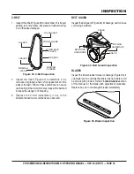
Figure 11. Throttle Cable Installation
5. Place the primary throttle return spring between
the cable housing clamp and the swivel stop screw
(Figure 11).
6. Feed the cable assembly through the cable housing
clamp, return spring, and swivel stop hole, until the
cable housing extends under the housing clamp to its
far edge (Figure 11).
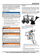
7. On the throttle lever, slightly loosen the locking nut and
cable retaining screw (Figure 10).
8. Make sure the throttle cable is seated in the throttle
cable receiver (Figure 10).
9. Route the throttle wire approximately 1/2 inch past the
cable retaining screw (Figure 10). Tighten the cable
retaining screw to secure the throttle wire.
10. Adjust cable tension as needed by loosening or
tightening the locking nut and cable retaining screw
on the throttle lever (Figure 10).
CABLE
END
SWIVEL
STOP
ADJUSTER
NUT
SWIVEL
STOP HOLE
CLAMP
SCREW
CABLE
HOUSING
CLAMP
CABLE
HOUSING
END
THROTTLE
CABLE
RETURN
SPRING
NOTICE
If the throttle lever does not return to the
neutral
position with the throttle backed off, loosen the adjusting
nut 1/2 turn at a time, tighten, and recheck. Readjust
throttle tension as necessary.
InstaClutch
™
Cable Installation
1. Uncoil the free end of the clutch cable.
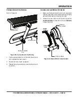
2. Make sure the clutch cable is attached to the torsion
bar cable anchor and clutch cable support bracket
(Figure 12).
Figure 12. Clutch Cable Attachment
(Torsion Bar Anchor and Support Bracket)
3. Make sure the clutch cable is fed along the underside
of the upper handle tube and secured to the main tube
with zip ties.
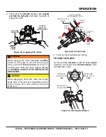
4. Using a 7/16" wrench, remove the three 1/4" retaining
bolts that secure the clutch cover to the frame
(Figure 13).
Figure 13. Clutch Cover Removal
CABLE
ANCHOR
TORSION
BAR
CLUTCH
CABLE
CLUTCH CABLE
SUPPORT BRACKET
BOLT (3)
CLUTCH COVER


