PRO46 SERIES WALK-BEHIND TROWEL • OPERATION AND PARTS MANUAL — REV. #1 (8/20/15) — PAGE 17
9.
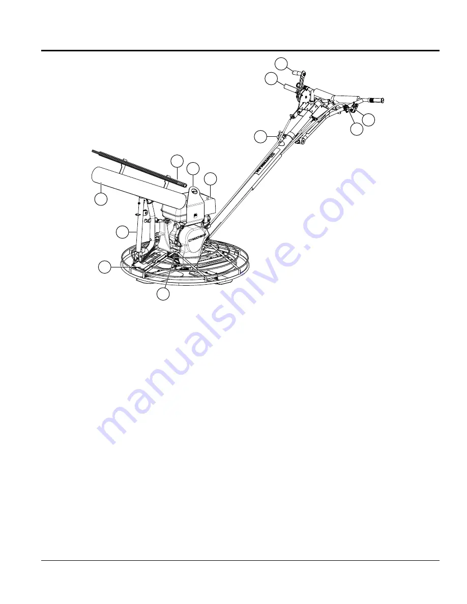
Gearbox
— Helical worm gear drive gearbox. Provides
rotation of blades via engine interface.
ALWAYS
check
gearbox oil level (sight glass) prior to each use. Fill with
recommended type gearbox oil.
10.
Access Panel
— Allows access to the blade area.
NEVER
run the trowel with this access panel removed.
11.
Mechanical Boom
— Works in conjunction with the
boom winch to either raise or lower the fresno blade/
brush. Has 180° range of rotation. Removeable weights
are provided to add stability.
12.
Fresno Blade
— Large troweling blade attached to the
mechanical boom arm. Provides a smooth finish over
large areas without the user having to walk out on the
troweling surface.
13.
Fresno Brush
— Large broom brush that is attached
to the fresno blade. Provides a textured or decorative
finish to the troweling surface.There are three different
color-coded, textured (stiffness) brushes compatible
with this trowel unit: soft (black), medium (orange) and
stiff (green).
TROWEL COMPONENTS
14.
Lifting Bale
— Attach a suitable lifting device to lifting
bale whenever lifting of the trowel is required.
15.
Engine
— Honda 11.0 HP gasoline engine. Reference
Table 3 for engine specifications.
16.
Star Wheel Knob (Handlebar Adjustment)
—
Changes the angle/height of the handlebar. Loosen
the star wheel (turn counterclockwise) to place the
handlebar in the desired position. Tighten the star
wheel (turn clockwise) to lock handlebar.
17.
Boom Winch
— Mechanical device used to raise or
lower the trowel boom arm. Rotating the crank handle
clockwise will lower the boom arm, and rotating the
handle counterclockwise will raise the boom arm.
18.
Throttle Lever
— Controls engine speed. May be
mounted on either side.
19.
Left Clutch Lever
— Squeeze to engage clutch.
4-blade rotation will start. This is the primary control
lever.
20.
Right Clutch Lever
— Pull up to engage the clutch.
4-blade rotation will start. This is the secondary control
lever.
13
14
18
20
19
12
11
9
10
17
16
15
Figure 3. Trowel Components (Continued)


