4
4.0 Flow Protection
Proof of chilled water and condenser water flow is required by the Master Control inputs. Paddle-type or Differential Pressure (DP) switches may be used.
Switches are a Multistack option, otherwise they are to field supplied and installed. Chillers purchased with chilled or condenser water pump modules have a
DP switch installed across the pump to verify it is running. Multistack recommends a paddle-type switch be installed in the leaving water piping of the chiller,
or if using a differential pressure switch install it across the inlet and outlet water connections to the chilled and/or condenser water piping connections.
5.0 System Water Volume
Chilled water systems remove the thermal gain from the process of cooling. A properly sized chilled water system will have enough time to properly control,
respond to changes in load, and prevent short cycling of the chiller. To ensure the system water volume is adequate, a general rule of thumb is:
7-10 gallons of water per ton
or
Acceptable Chilled Water Volume = Chilled Water Design GPM X 3
In the event the system components can’t hold the necessary chilled water volume, a properly sized chilled water storage tank should be added.
6.0 Electrical Data
Field wiring should be done in accordance with all federal, state and local regulations. Breakers, fuses, wire, and wire size must be sized and installed per the
National Electric Code (NEC). Applied voltage to all Multistack chillers must be ± 10% of the unit’s nameplate voltage. The voltage imbalance between phases
must not exceed 2%. According to NEMA Standard MG-1-1998, a 2% voltage imbalance will cause a current imbalance of 6 to 10 times the voltage imbalance.
It is very important to keep the unbalance between electrical phases to a minimum.
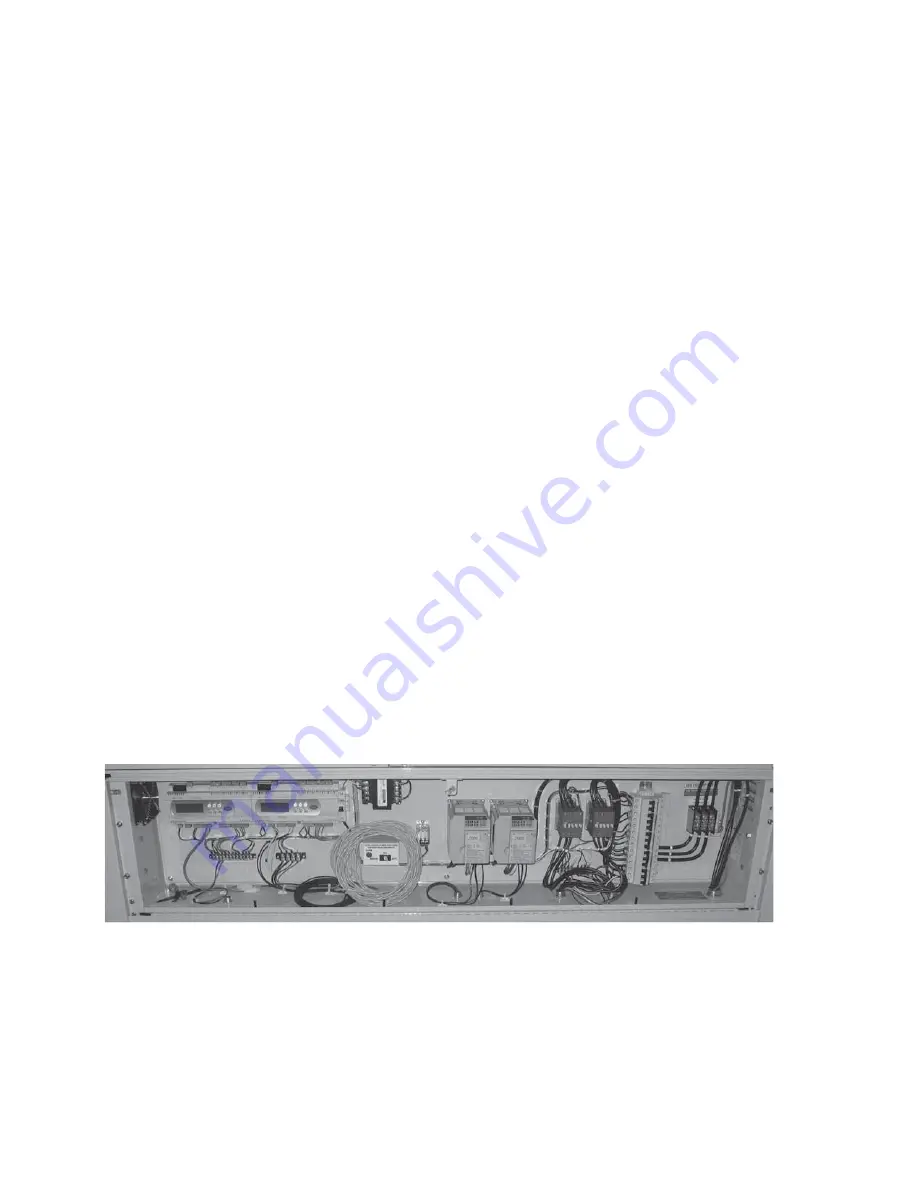
There will always be one module in the bank that is the Master Module. This module contains the Master Control Board (far left) as well as the module Slave
Board (right of the master). Condenser fan control will either be by on/off pressure control or VFDs. Compressors use contactors as starters and circuit breakers
for high and low voltage components. The main power input block is located to the right of the circuit breakers. A module Auto / Off / Manual Mode switch
is also available for back up control if the master board would fail. The master module also has the terminal strip inputs for flow switches, start/stop, alarm
output, and phase monitor. When shipped the master control panel will also contain the P-Lan communication wire to be field installed and the system
Leaving Chilled Water Sensor well to be field installed.
7.0 Identification and Explanation of Components
7.1 Master Module Control Panel
There will always be one module in the bank that is the Master Module. This module contains the Master Control Board (far left) as well as the module Slave
Board (right of the master). Condenser fan control will either be by on/off pressure control or VFDs. Compressors use contactors as starters and circuit breakers
for high and low voltage components. The main power input block is located to the right of the circuit breakers. A module Auto / Off / Manual Mode switch
is also available for back up control if the master board would fail. The master module also has the terminal strip inputs for flow switches, start/stop, alarm
output, and phase monitor. When shipped the master control panel will also contain the P-Lan communication wire to be field installed and the system
Leaving Chilled Water Sensor well to be field installed.


