SPECIFICATIONS
Conduit
®
300 Series IoT Programmable Gateway MTCDT3AC-L4G1/-EN Hardware Guide
15
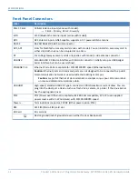
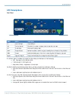
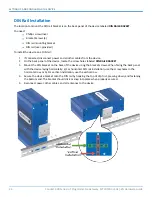
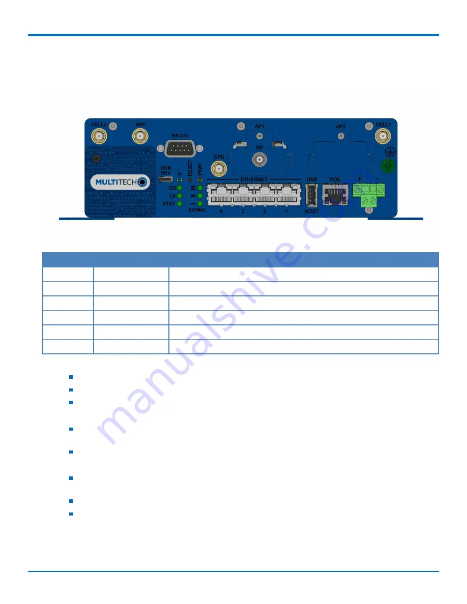
LED Descriptions
Front Panel
Label
Name
Description
A
User-defined
User-defined.
CD
Carrier Detect
This LED is on when a cellular data connection is made.
LS
Link Status
Varies with radio model.
STAT
Power Status
Default condition: LED turns green (solid) when software is fully loaded.
PWR
Power
Solid (constant) green if unit is on indicating that DC power is present.
Signal
Signal Strength
These 3 LEDs display the strength of the cellular signal.
If a cellular radio is installed, the typical LS (Link Status) LED behavior is the following:
OFF - No power to the cellular radio
Continuously Lit - Not registered
Slow Blink (-0.2Hz) - Registered or connected
For the RJ-45 Ethernet LEDs (located at the top of the connector) are defined as follows:
Yellow LED (lower-left) indicated activity/link. Blinks when there is transmit and receive on the Ethernet
link.
Green LED (lower-right) when solid indicates link on.
On the front panel, the POE LEDs (located at the bottom of the connector) are defined as follows:
Yellow LED (lower-left) indicated activity/link. Blinks when there is transmit and receive on the Ethernet
link.
Green LED (lower-right) when solid indicates link on.
Orange LED (lower-right) indicates POE supply was connected that was not 25W minimum power


