GETTING STARTED
24
Dragonfly
TM
MTQ-LSP3-B03 Device Guide
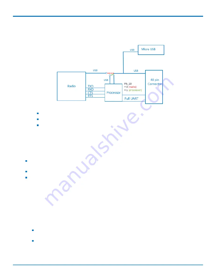
Communications Flow
Processor Model (B03)
Note:
The device has a UART subset as well as GPIO (4 pin UART (tx/rx/rts/cts)
If needed, use the GPIOs for additional UART signaling.
The USB port can switch between a connection to the radio (red dotted line) or a connection to the
processor (green x line). The USB selection is controlled via programming on the processor. There is
no USB between the radio and the processor.
Communicating with the Device
Following are three options for communicating with the device.
Recommended:
Establish serial communication using MultiTech developer board MTUDK2. See the
Universal
Developer Kit 2.0 Developer Guide
(PN S000610) for more information.
Install cellular radio USB drivers and plug into the micro USB connector. No need for a host board.
Install cellular radio USB drivers. Access the device's USB interface via pins 6 and 7 of the 40-pin connector.
Data pins 6 and 7 are in parallel with the micro USB connector on the device. There is no connection to pins
6 and 7 on the developer board.
Device Drivers
Note:
Install drivers on your computer before connecting the device.
For the UDK2 Developer Board, download the driver through the developer kit page Downloads tab at
https://www.multitech.com/brands/socketmodem-dragonfly-dev-kit
. The installation instructions are included in
the driver zip file.
For the MTQ, the cellular radio USB device driver is available on your model's page.
Go to
https://www.multitech.com/brands/multiconnect-dragonfly
and click on your model. Download
the driver from Downloads.
The USB Driver Installation Guide (S000616) is included in the driver download and is also available
under Manuals on your model's page.


