background image

MT467 User Guide

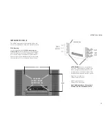
INSTALLING THE CELL (I)

The MT467 display must be installed before use. 
Choose an installation setup among the following.


VESA Mounting

In concordance with the 

VESA Mounting Interface 

Standard (MIS-F)

, the Cell features in its back panel 

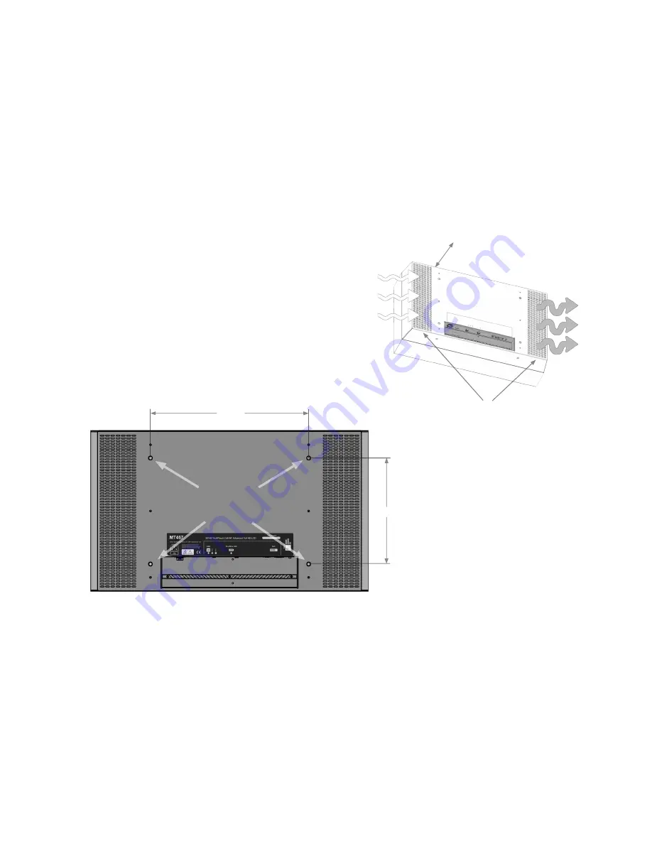
four (4) screw holes of the VESA M8 MIS-F 600, 
400, 8 type. Attach any pedestal or wall mount 
that conforms to the standard, always observing 
the requirements for cooling and air ventilation.

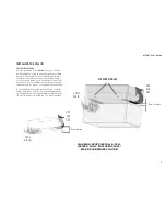
ATTENTION:

 Maintain the ventilation 

slots free of blockages at all times and 
leave enough space behind the Cell to 
allow proper air circulation and cooling 
between the display and walls or panels:  
 
Single Cell installations 
at least 10 cm (4 inches) 
 
Multi-Cell installations 
at least 15 cm (6 inches) 
 

Heat build-up reduces the system’s 
life and can cause hardware failure.

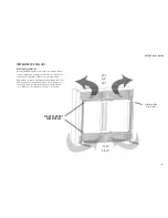
HOT

AIR

OUT

COOL

AIR IN

600 mm

400 mm

STANDARD

M8 VESA MOUNT

SCREW HOLES (4)

CLEARANCE AREA

6

Summary of Contents for MT467

Page 1: ...MT467 User Guide Version 2 0 MULTITOUCH LTD Kiviaidankatu 2 B 00210 Helsinki Finland www multitouch fi 358 45 630 8580 ...

Page 2: ...5 Installing the Cell VESA mount 6 Installing the Cell custom install 7 Installing the Cell multi cell 8 Connecting the Cell 9 Operations Guideline 10 Cleaning the Cell 11 The next steps 11 Calibration 11 Online Resources 11 The Cornerstore Software 11 Cell Dimensions 13 Technical specifications 14 Warning Labels 16 2 ...

Page 3: ...LCD displays deliver Full HD picture quality have a long life span and need hardly any maintenance Modular means that Cells can be easily connected to each other to create a single large display array showing interactive content split into the various screens while reacting to multiple users touch The system welcomes customisation Work on Linux Mac or Windows environments and create your own tailo...

Page 4: ......

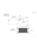
Page 5: ... its shipping box 5 1 Bend all the metal tabs on top of the box 3 Bend all the metal tabs on the side of the box 2 Remove the top cover 4 Remove the side cover 5 Remove the protective foam 6 Remove the Cell from the box ATTENTION It is recommended that the Cell be removed by two persons one from each side ...

Page 6: ...nforms to the standard always observing the requirements for cooling and air ventilation ATTENTION Maintain the ventilation slots free of blockages at all times and leave enough space behind the Cell to allow proper air circulation and cooling between the display and walls or panels Single Cell installations at least 10 cm 4 inches Multi Cell installations at least 15 cm 6 inches Heat build up red...

Page 7: ...d to secure the display into a custom enclosure that will encase it from all sides Carefully observe the requirements for proper cooling and air ventilation A simplified custom setup would consist of sturdy supporting legs on each side firmly wrapping the Cell and keeping it at the minimum safety distance 15 cm 6 inches from the top of a stable surface 7 WARNING NEVER INSTALL A CELL INSIDE A FULLY...

Page 8: ...ll two or more Cells together to operate in Multi Cell configuration Remember to leave enough space between the Cells and any walls or panels behind to allow proper air circulation and cooling minimum safety distance for a Multi Cell installation is 15 cm 6 inches 8 HOT AIR OUT COOL AIR IN CLEARANCE AREA 15 cm 6 inches M8 VESA MOUNT SCREW HOLES ...

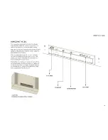
Page 9: ...C A U T I O N D O U B L EP O L E N E U T R A L F U S I N G ...

Page 10: ...nt on the display and remain permanently As prevention combine the following ATTENTION AVOID DIRECT SUNLIGHT ON THE DISPLAY AREA FRONT PANEL t Run an application that regularly changes the screen s contents alternating from static images to moving pictures this helps refresh the display s liquid crystal Periodical changes in background color and character are also recommended t Enable a screen sav...

Page 11: ...cornerstone multitouch fi calibration Troubleshooting For troubleshooting instructions http cornerstone multitouch fi troubleshooting Support For online support on MultiTouch Cells http cornerstone multitouch fi support form SDK Tutorials For information regarding the SDK to compile new applications etc http cornerstone multitouch fi sdk tutorials sdk tutorials MT467 User Guide THE CORNERSTORE SOF...

Page 12: ...hem in the file manager or via the command prompt d CornerStone runtime or SDK package from the Cornerstone download section for example Cornerstone Runtime 1 1 2 dmg 2 Copy the MT467 configuration file to the correct location i e from Library Frameworks MultiTouch framework data Configs config mt467 txt to Users joe Library MultiTouch config txt 3 Start Twinkle Collisions or any other application...

Page 13: ...MT467 User Guide 13 MULTITOUCH MT467 DIMENSIONS 255 mm 162 mm 605 mm 400 mm 137 mm 2 x M8 4 x M8 2 x M8 600 mm 600 mm 600 mm 1052 mm 299 mm 1000 mm 514 mm 116 mm ...

Page 14: ...e 400 6 pin Power Connector IEC C14 ELECTRICAL SPECIFICATIONS Power Supply 100 240 VAC 50 60 Hz Power Consumption 300 W typical 400W max TOUCH DETAILS Tracking Software MultiTouch Cornerstone Engine included installed on a connected computer 2 Touch Input Types Single finger multiple fingers single hand multiple hands and users objects with optical markers Click hold and drag TOUCH DETAILS Hand Re...

Page 15: ... dBA MISCELLANEOUS Agency Approvals CE RoHS Compliant Yes Expected Life time Over 60 000 hours Warranty 1 Year SALES PACKAGE CONTENTS Display Unit MT467 Power Cords 5 m EUR US GB Digital Video Cable DVI D 5 m USB A B Cable 5 m FWire IEEE 1394 6 6 pin 4 m Product Manual English version Warranty Card Quick Start Guide NOTES When used with MultiTouch 1 Cornerstone tracking software Computer not inclu...

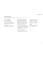
Page 16: ...MT467 User Guide MULTITOUCH MT467 WARNING LABELS 16 ...

Reviews: