5. ELECTRICAL WIRING
İ
CAUTION
● Design a dedicated power supply for the indoor unit and outdoor unit.
● If the power supply uses a branch loop, install an electricity leakage protector and a manual switch.
● The power supply, electric leakage protectors, and manual switches of the indoor units that connect to the same
outdoor unit must be universal. Use the same loop for the indoor unit power connect to the same outdoor unit
must be universal. Use the same loop for the indoor unit power supplies in the same system. Power on/off at the
same time.
● Incorporate the outdoor unit and indoor unit connection wiring system and refrigerant pipe system for the same
system.
● To reduce interference, use a three-core shielded twisted pair as the outdoor unit signal cable. Do not use a
multi-core cable.
● Complete wiring according to national electrical standards.
● Employ an electrical engineer for wiring.
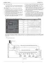
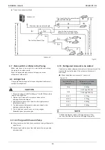
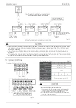
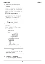
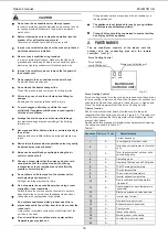
200/224/260 Three-phase electrical control system connection of the outdoor unit
P Q E
L N
P Q E
L N
P Q E
L N
P Q E
L N
B C N
A
K2
K2 E O
K1
K1
A E
Y
E P
X
Q E
Power supply for the outdoor unit monitor
Outdoor unit
Outdoor unit monitor
(Optional)
L N
L N
K1 K2 E
K1 K2 E
Digital ammeter power supply
Digital ammeter
(Optional)
L N
L N
O A E
O A E
Power supply for the central indoor
unit controller
central indoor unit
controller(Optional)
L N
L N
X Y E
X Y E
Outdoor power supply
Outdoor power
supply
Indoor unit
Indoor unit
Indoor unit
Indoor unit
Distribution box
Distribution box
Distribution box
Distribution box
Switch
Switch
Fuse
Fuse
Fuse
Fuse
Fuse
Use a shielded cable and ground
the shielding layer
CAUTION
An incorrect connection configuration may damage the compressor or other components.
PQE is a signal cable, which must be connected to a weak current. Do not connect it to strong current.
All wiring terminals must be securely fixed. The grounding wire must be grounded as required.
After connecting to the connector base, the power cable must be securely fixed.
After all wires are connected, check the correctness all components before powering on.
Fig.5-1
3000
11
Installation manual
Mini MVD V4+


