background image

Ducted Split Type Air-Conditioning

13

5.11 E-heater setting *

There is no this function for this unit  

E-heater: In heating mode, E-heater is allowed to be turned on for improvement of efficiency. 

If heating mode is turned on by button operation, auxiliary electric heating function will be automatically 

turned on. 

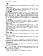
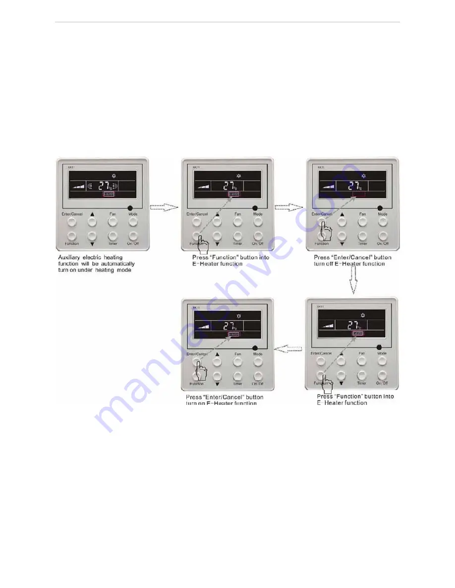
Press Function button in heating mode into auxiliary electric heating function, E-HEATER blinking, and 

press Enter/cancel button to turn on this function. In this case, E-HEATER will be displayed, which means 
E-heater is allowed to be turned on. 

If auxiliary electric heating function is on, press Function button to confirm or press Enter/cancel button to 

cancel. In this case, E-HEATER won’t be displayed, which means E-heater is prohibited to be turned on. 

The setting of this function is shown as Fig.5.11 below:

Fig. 5.11  Auxiliary Electric Heating Function Setting

Note: 

1)  E-heater can not be set in cooling, dry and fan mode, E-heater mark won’t be displayed. The setting is 

shown in Fig.5.11.

2)  There is not E-heater for A2 and cassette unit.

Summary of Contents for MUCH-20-H4

Page 1: ...ucted Split Type MUCH 20 H4 MUCH 25 H4 MUCH 30 H4 MUCH 40 H4 Air Conditioning Units Please read this manual carefully before using this product and keep it properly for future reference Applicable Mod...

Page 2: ...cope of guarantee must accord with the following items The first start up should be carried out by qualified service technicians appointed by the service center of MUNDOCLIMA The components of air con...

Page 3: ...of Wired Controller and Project Debugging 5 4 1 Installation of Wired Controller 5 5 Instruction to Operation 6 5 1 On Off 6 5 2 Mode Setting 6 5 3 Temperature Setting 6 5 4 Fan Speed Setting 7 5 5 S...

Page 4: ...1 10 Installation instruction 22 10 1 Selection proper installation location 22 10 2 Install the indoor unit 23 10 3 Install the outdoor unit 27 10 4 Electric wiring 30 11 Trial run and installation c...

Page 5: ...re the power supply correspond to the nameplate and check the security of the power source before installation Make sure that the wires pipes and drain hose are properly connected before operation to...

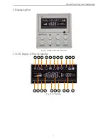
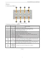
Page 6: ...Ducted Split Type Air Conditioning 2 2 Displaying Part Fig 2 1 Outline of wired controller 2 1 LCD Display of Wired Controller 1 2 3 4 5 6 7 8 9 10 11 12 13 14 15 16 17 18 19 20 21 Fig 2 2 LCD display...

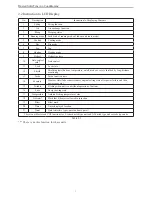
Page 7: ...ff mode or save is shielded by long distance monitoring 13 Turbo Turbo function state 14 Memory Memory state Indoor unit resumes original setting state after power failure and then power recovery 15 T...

Page 8: ...urbo save e heater blow quiet 7 Timer Timer setting 8 On off Turn on off indoor unit 4 Mode and 2 Memory function Press them for 5s under off state of the unit to enter cancel memory function If memor...

Page 9: ...hole at the back of controller s soleplate 3 Joint the controller s soleplate on wall face and then fix it in mounting hole with screws M4X25 4 Insert the 4 core twisted pair through rectangle hole i...

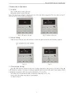
Page 10: ...ode Setting Under on state of the unit press Mode button to switch the operation modes as the following sequence Fig 5 2 1 Fig 5 3 5 3 Temperature Setting Press or button for increase or decrease of s...

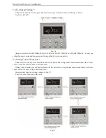
Page 11: ...e and fan speed can t be modified by wired controller 5 5 Swing Control Function Under on state of unit press Function button till the unit enters swing control function and then press Enter cancel bu...

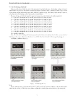
Page 12: ...imer to confirm If Mode button is pressed before pressing Timer button to confirm timer mode will be switched to timer on setting mode In this case LCD displays xx Hour ON blinking In this case press...

Page 13: ...min 4 The unit continuously runs for 60min and fresh air valve runs for 2 4 min 5 The unit continuously runs for 60min and fresh air valve runs for 30 min 6 The unit continuously runs for 60min and fr...

Page 14: ...ng is shown as Fig 5 8 Fig 5 8 Sleep setting Sleep off is default after power failure and then power recovery There is not sleep function in fan and auto mode Note In cooling and dry mode if the unit...

Page 15: ...s Enter cancel button to turn on turbo function During turbo function press Function button till the unit enters turbo function and then press Enter cancel button to cancel turbo function Turbo functi...

Page 16: ...or button to adjust upper limited value of setting temperature in heating mode After that press Enter Cancel button to turn on energy saving function for heating After energy saving function is turned...

Page 17: ...cancel button to turn on this function In this case E HEATER will be displayed which means E heater is allowed to be turned on If auxiliary electric heating function is on press Function button to co...

Page 18: ...ton to turn on this function In blow mode press Function button till the unit enters blow function and then press Enter cancel button to cancel this function Dry function setting is shown in Fig 5 12...

Page 19: ...uiet function fan speed is un adjustable 2 When turning on auto quiet function the unit will enter quiet running state according to temperature difference between room temperature and setting temperat...

Page 20: ...ng won t be saved 5 15 Other Functions 5 15 1 Lock Function Upon startup of the unit without malfunction or under off state of the unit press and buttons at the same time for 5s till the wired control...

Page 21: ...multiple systems the system number of failed system will be displayed before the colon not for single system If malfunction occurs please turn off the unit and ask professionals for help As shown in...

Page 22: ...he mode will be changed in a regular as AUTO COOL DRY FAN HEAT AUTO COOL DRY FAN HEAT 3 button Press the or button to set your desired temperature The temperature range is from 16 to 30 It is not nece...

Page 23: ...ow on or off the characters of Blow will appear of disappear by pressing this key under cooling or dehumidify mode Once energized the unit will be defaulted to be Blow off Set E Heater on or off the c...

Page 24: ...use the malfunction of the wireless remote control If the wireless remote control will not be used for a long time please take them out and do not let the leakage liquid damage the wireless remote con...

Page 25: ...fter connected to power the WEEKLY TIMER can display all connected units sequence of unit is determined by code switch of manual control of every duct type unit On and off of every duct type unit can...

Page 26: ...als And don t supply power until all the work is finished according to the user s manual 10 1 Selection proper installation location 1 Selection the proper location for indoor unit Avoid the direct su...

Page 27: ...proof interfere the ventilation of outdoor unit 10 2 Install the indoor unit 1 The dimensions of installation hole and the intake outlet port are shown in Fig 19 and Table 1 a d c b f e Air Outlet b...

Page 28: ...thermal insulation material A water seal should be employed as shown in Fig 19 and the height of the water seal could be determined by the pressure of the drain hose Drain hose is in negative pressure...

Page 29: ...position of the wall should be reserved for the connection signal cables The connection wire between indoor unit and controller can be laid in the pit with 1 PVC pipe for direct installation Figure 22...

Page 30: ...room sensors One is located at the air intake of the indoor unit and the other one is located inside the wire controller User can select one from the two indoor room sensors on the basis of the engin...

Page 31: ...of the belt should be adjusted again we should routinely check it every 1 2 months also ensure the test results complying with Table 2 The adjustment of the tightness of the belt is shown in Fig 25 L...

Page 32: ...utdoor unit A B C 193 488 287 360 Fig 27 Schematic of the Outdoor unit Model A mm B mm C mm MUCH 20 H4 1150 422 1350 MUCH 25 H4 1150 422 1600 1772 A 880 840 C 2 B 2 844 2 Fig 28 Schematic of the Outdo...

Page 33: ...schematic When removing the outdoor unit two ropes are needed to hang the unit along the four ways In order to avoid the excursion the angle between the ropes should be less than 40 degree Please use...

Page 34: ...The air is evacuated in the pipe from the check valve with a vacuum pump if no leakage exists then loosens the cores of the liquid valve and gas valve and clears the soap water with dry cloth If the...

Page 35: ...ystem should be installed Wiring diagram of the ducted air conditioning unit is shown in Fig 32 The units should be well earthing to the ground by professionals Install a central switch which can cut...

Page 36: ......

Page 37: ......

Page 38: ......

Page 39: ...it been fixed firmly How is the installation The unit may drop shake or emit noise Have you done the refrigerant leakage test It may cause insufficient refrigerating capacity Is heat insulation suffic...

Page 40: ...CLIMA 4 Check if it s necessary to operate the air conditioner 5 Connect it properly 6 Contact the service center of MUNDOCLIMA Heating is not sufficient 1 Air filter is blocked 2 Air outlet port or i...

Page 41: ...pipe regularly so as to confirm the fluency flow of condensate 5 Running cautions of machine as operating season coming Check if air intake and outlet port is blocked Check if the earth connection of...

Page 42: ...eters are subject to change with the improvement of products in which case the values on nameplate shall prevail 4 In this table the outdoor side 18 15 DB temperature of low ambient cooling include tw...

Page 43: ...Proven a 392 pl 2 08025 Barcelona Tel 93 446 27 80 Fax 93 456 90 32...

Reviews: