© Munters AB, 2018
•
Key:
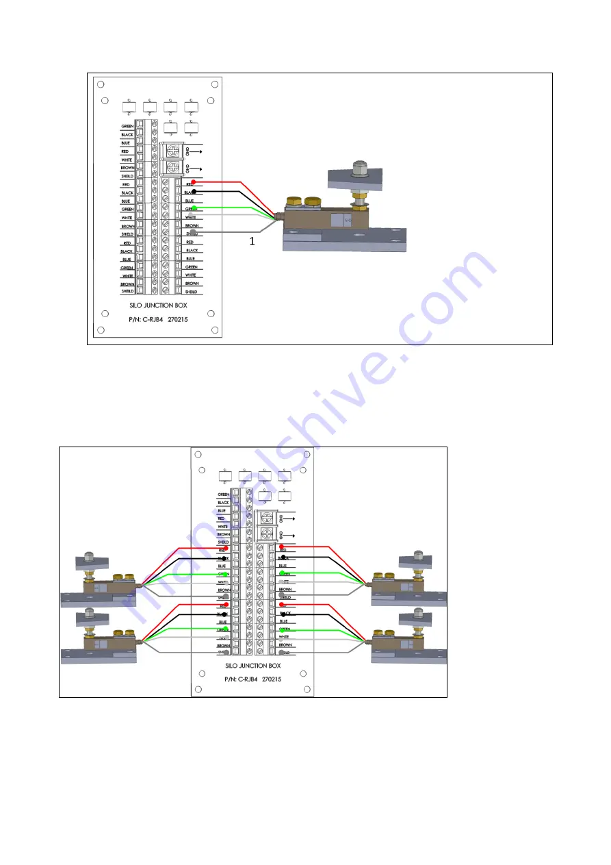
1: Shield wire
Figure 1: RJB-4 to Load Cell Wiring Diagram
2. Repeat for each load cell.
NOTE:
The RJB-4 can support more than one load cell on each terminal. To connect more than four
load cells to the RJB-4, place a second set of load cell wires into each terminal load cell block.
Figure 2 illustrates four load cells connected to the RJB-4.
Figure 2: RJB-4 Connected to Four Silos
3. The RSW-2 cell has a 4-wire shielded cable. Run these wires from the RSW-2 Silo A
terminal block to the RJB-4 controller terminal block; attach each wire to the input slot with
same color. For example, connect the red wire to the red input slot. Figure 3 illustrates the
wiring.


