v.090220
13
ENGLISH
PARTS LIST
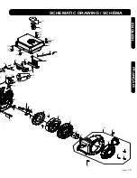
Please refer to the schematic drawing on pages 14 & 15.
N
O.
DESCRIPTION
QTY.
1
Bolt
7
2
Oil seal Φ35 x φ52 x 7
1
3
Crankcase cover
1
4
Dipstick cap
1
5
Dipstick gauge
1
6
O ring
2
7
Dipstick seat
1
8
Bolt
1
9
Dipstick assy.
1
10
Oil plug assy.
2
11
Crankcase gasket
1
12
Bearing 6202(P6)
1
13
Dowel pin φ9 x 14
1
14
Dowel pin φ7 x 14
1
15
Camshaft components
1
16
Balance shaft
components
1
17
Crankshaft assy.
1
18
Driven gear assy.
1
19
Oil seal Φ35 x φ52 x 7
1
21
Drain oil pipe assy.
1
22
Bearing 6202(P6)
1
23
Ignition assy.
1
24
Bolt
2
25
Magneto
1
26
Bolt
2
27
Flywheel assy.
1
28
Fan
1
29
190F Start pulley
1
30
Nut
1
31
Shroud
1
32
Recoil cover assy.
1
33
Bolt
3
34
Recoil starter assy.
1
35
Bolt
4
36
Cotter pin
1
37
Gasket φ8 x φ20 x 0.8
1
38
Throttle governor arm
1
39
Dowel pin φ12 x 20
2
40
Exhaust valve
1
41
Intake valve
1
N
O.
DESCRIPTION
QTY.
42
Valve lifter
2
43
Push rod
2
44
183F cylinder head seal
1
45
Cylinder head assy.
1
46
Spark plug F7RTC
1
47
Double-end bolt/power
M8x48.5
2
48
Exhaust gasket/power/
no asbestos
1
49
Bolt M10 x 1.25 x 80
4
50
Oil shield assy.
1
51
Valve spring seat
1
52
Valve spring
2
53
Exhaust valve spring
seat
1
54
Intake valve spring seat
1
55
Exhaust valve adjusting
cap
1
56
Rocker arm seat
1
57
Pin nut
2
58
Valve rocker arm
2
59
Valve gap adjusting nut
2
60
Lock nut
2
61
Gasket
1
62
Cylinder head cover
1
63
Bolt M6 x 14
4
64
182F muffler
1
65
Nut M8
2
66
Exhaust pipe
1
67
Clamp
1
68
In.pipe double-end bolt
M6-8 x 134 182F
2
69
Carburetor heat
insulation gasket
1
70
Carburetor heat
insulation /power
1
71
Carburetor gasket
1
72
Air filter gasket
1
73
Carburetor assy.
1
74
Air filter assy.
1
75
Nut M6
2
76
Crankcase
1
77
Piston ring assy.
1
N
O.
DESCRIPTION
QTY.
78
Piston pin stopper
2
79
Wrist pin
1
80
Piston
1
81
Connecting rod assy.
1
82
Air deflector
1
83
Bolt M6 x 12
1
84
Bolt M6 x 12
1
85
Nut M6
1
86
Throttle bracket
1
87
Governor spring
1
88
Throttle return spring
1
89
Throttle control rod
1
90
Throttle control assy.
1
91
Governor arm sleeve
1
92
Fuel tank cap assy.
1
93
Fuel filter
1
94
Fuel tank assy.
1
95
Nozzle
1
96
188F clamp
2
97
Gas line φ6.3 x φ12.5
x 300
1
98
Front fuel tank mounting
bracket 190F
1
99
Rear fuel tank mounting
bracket 190F
1
100
Bolt M8 x 14
4
101
Bolt M8 x 20
4
102
Shock absorber gasket
for fuel tank
2
103
Shock absorber gasket
sleeve
2
104
Shock absorber gasket
2
105
F shock absorber
gasket sleeve
2
106
Starter motor assy.
1
107
Bolt M4 x 55
2
108
Bolt M8 x 55
2
109
Oil sensor
1
110
Oil annunciator and
protection amplifier
1
111
Shutdown switch assy.
1
Summary of Contents for WSG112
Page 22: ...22 WSG112 ENGLISH FRANÇAIS ...
Page 23: ...v 090220 23 FRANÇAIS ENGLISH SCHEMATIC DRAWING SCHÉMA ...
Page 24: ...24 WSG112 ENGLISH FRANÇAIS SCHEMATIC DRAWING SCHÉMA ...
Page 25: ...v 090220 25 FRANÇAIS ENGLISH SCHEMATIC DRAWING SCHÉMA ...
Page 59: ...12 WSG112e ENGLISH ...
Page 61: ...14 WSG112e ENGLISH FRANÇAIS SCHEMATIC DRAWING SCHÉMA ...
Page 62: ...v 090220 15 FRANÇAIS ENGLISH SCHEMATIC DRAWING SCHÉMA ...


