■
Soldering and Mounting
1.Mounting Position
1. Confirm the best mounting position and direction that minimizes the stress imposed on the capacitor during flexing
or bending the printed circuit board.
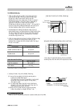
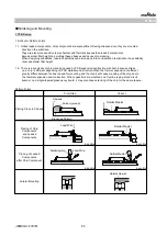
1-1.Choose a mounting position that minimizes the stress imposed on the chip during flexing or bending of the board.
[Component Direction]
Locate chip horizontal to the
direction in which stress acts.
[Chip Mounting Close to Board Separation Point]
It is effective to implement the following measures, to reduce stress in separating the board.
It is best to implement all of the following three measures; however, implement as many measures as possible
to reduce stress.
Stress Level
(1) Turn the mounting direction of the component parallel to the board separation surface.
A
>
D
(2) Add slits in the board separation part.
A
>
B
(3) Keep the mounting position of the component away from the board separation surface.
A
>
C
[Mounting Capacitors Near Screw Holes]
When a capacitor is mounted near a screw hole, it may be affected by the board deflection that occurs during
the tightening of the screw. Mount the capacitor in a position as far away from the screw holes as possible.
2.Information before Mounting
1. Do not re-use capacitors that were removed from the equipment.
2. Confirm capacitance characteristics under actual applied voltage.
3. Confirm the mechanical stress under actual process and equipment use.
4. Confirm the rated capacitance, rated voltage and other electrical characteristics before assembly.
5. Prior to use, confirm the solderability for the capacitors that were in long-term storage.
6. Prior to measuring capacitance, carry out a heat treatment for capacitors that were in long-term storage.
7.The use of Sn-Zn based solder will deteriorate the reliability of the MLCC.
Please contact our sales representative or product engineers on the use of Sn-Zn based solder in advance.
Caution
Contents of Measures
Screw Hole
Recommended
!
①
②
③
1C 1B
1A
Perforation
Slit
A
B
C
D
①
1A
JEMCGC-2701W
15


