background image


MFX-C4000 


Field Engineering Manual 

U.S.A. version 1.0 


Muratec America, Inc. 

3301 East Plano Parkway, Ste. 100 

Plano, TX 75074 

(469) 429-3300 (tel) 

 (469) 429-3465 (fax) 

www.muratec.com 

Summary of Contents for MFX-C4000

Page 1: ...MFX C4000 Field Engineering Manual U S A version 1 0 Muratec America Inc 3301 East Plano Parkway Ste 100 Plano TX 75074 469 429 3300 tel 469 429 3465 fax www muratec com ...

Page 2: ......

Page 3: ...gine 2 3 2 2 2 Controller S W 2 3 2 2 3 Scan 2 5 2 2 4 Copy 2 6 2 2 5 FAX 2 7 2 2 6 Paper Handling 2 9 2 2 7 Consumables CRU 2 11 2 2 8 Consumables FRU 2 12 2 2 9 Reliability Service 2 12 2 2 10 Options 2 13 2 3 System Overview 2 14 2 3 1 System Configuration 2 18 2 3 2 H W Configuration 2 19 2 3 3 Mechanic Configuration 2 37 3 Disassembly and Reassembly 3 1 Maintenance 3 1 3 1 1 Precautions on Ma...

Page 4: ...ing 4 1 Alignment and Adjustments 4 1 4 1 1 Paper path 4 1 4 1 2 Clearing paper Jam 4 2 4 1 3 Abnormal Image Printing and Defective Roller 4 16 4 1 4 Control Panel overview 4 19 4 1 5 Understanding the Status LED 4 22 4 1 6 Menu overview 4 23 4 1 7 Firmware Upgrade 4 34 4 1 8 Diagnostics 4 38 4 2 Troubleshooting 4 68 4 2 1 Procedure of Checking the Symptoms 4 68 4 2 2 Display Meassage Troubleshoot...

Page 5: ...5 10 Pick Up Ass y 5 31 5 11 Frame Lower1 5 33 5 12 Frame Lower2 5 36 5 13 Bottle Base 5 38 5 14 Registration 5 40 5 15 Guide REGI 5 42 5 16 Holder OPC 5 44 5 17 HV DEVE 5 46 5 18 WTB Motor 5 48 5 19 Toner Drive 5 50 5 20 LSU Cleaning 5 52 5 21 Frame Upper 5 54 5 22 Guide Exit 5 56 5 23 Front OPC Unit 5 58 5 24 Exit Ass y 5 60 5 25 Fuser_LV Unit 5 62 5 26 Cartridge_Transfer 5 65 5 27 Pusher_LSU 5 ...

Page 6: ...SCF 5 103 5 44 1 Main_Finisher 5 107 5 44 2 Frame Unit 5 109 5 44 3 Stacker Unit 5 112 5 44 4 Extension Tray Unit 5 114 5 44 5 Ejector Unit 5 116 5 44 6 Compile Unit 5 119 5 44 7 Feed Unit 5 121 5 45 HCF UNIT Optional Unit 5 124 5 45 1 ELA HOU HCF 5 124 5 45 2 SUB PLATE BOTTOM 5 127 5 45 3 SUB UNIT REAR 5 129 5 45 4 AS UNIT FRAME RIGHT 5 131 5 45 5 ELA HOU UPPER 5 133 5 45 6 AS UNIT CASSETTE 5 136...

Page 7: ...Video Controller 6 7 6 2 2 Engin Controller 6 8 6 2 3 OPE Unit 6 9 6 2 4 DADF 6 10 6 2 5 SCF HCF 6 11 7 Reference Information 7 1 Tool for Troubleshooting 7 1 7 2 Acronyms and Abbreviations 7 2 7 2 1 Acronyms 7 2 7 2 2 Service Parts 7 4 7 3 A4 ISO 19798 Standard Pattern 7 8 7 4 Wireless LAN 7 13 7 5 Model Information 7 14 7 5 1 Understanding for Model Code 7 14 7 5 2 Understanding Material Code Na...

Page 8: ...unit Second Cassette Feeder Optional tray 8 18 8 2 5 HCF unit High Capacity Feeder 8 20 8 2 6 Stand Tall Small 8 22 8 2 7 Finisher 8 25 8 2 8 FDI Foreign device interface 8 30 8 3 Setting up the network 8 32 8 3 1 Supported operating systems 8 32 8 3 2 Configuring network protocol via the machine 8 33 8 3 3 Configuring network protocol by using the SetIP program 8 35 ...

Page 9: ...ectric shock or fire haz ards 3 Laser Safety Statement The Printer is certified in the U S to conform to the requirements of DHHS 21 CFR chapter 1 Subchapter J for Class 1 1 laser products and elsewhere it is certified as a Class I laser product con forming to the requirements of IEC 825 Class I laser products are not considered to be hazardous The laser system and printer are designed so there is...

Page 10: ...nserting or removing the power connector The power connector must be inserted completely otherwise a poor contact could cause overheating possibly leading to a fire When removing the power connector grip it firmly and pull 7 Take care of the power cable Do not allow it to become twisted bent sharply round corners or other wise damaged Do not place objects on top of the power cable If the power cab...

Page 11: ...t the following procedures before dismantling the printer or replacing any parts 1 Check the contents of the machine memory and make a note of any user settings These will be erased if the mainboard or network card is replaced 2 Ensure that power is disconnected before servicing or replacing any electrical parts 3 Disconnect printer interface cables and power cables 4 Only use approved spare parts...

Page 12: ...ximately 78 Kg including consumables therefore pay full attention when handling it Be sure not to hold the movable parts or units e g the control panel DADF when transporting the equipment Be sure to use a dedicated outlet with 110V 220Vpower input The equipment must be grounded for safety Select a suitable place for installation Avoid excessive heat high humidity dust vibration and direct sunligh...

Page 13: ...charges sufficient to damage ESDs 5 Do not use Freon propelled chemicals When sprayed these can generate electrical charges sufficient to damage ESDs 6 Do not remove a replacement ESD from its protective packaging until immediately before installing it Most replacement ESDs are packaged with all leads shorted together by conductive foam aluminum foil or a comparable conductive material 7 Immediate...

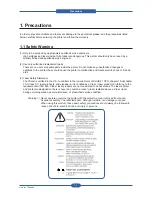
Page 14: ...Precautions Service Manual 1 6 ...

Page 15: ... High Speed Single Path Color MFP Document Management Center Machine for Mid Large Workgroup Click Charge Business model for Customers Additional Reseller Revenue via Supplies Service Contract Color Touch Screen UI Easy Installable Set Options High Performance Fully Featured CMFP with Competitive TCO Simple Jam Recovery Features Automatic Toner Ordering Systems Durability better than competitions ...

Page 16: ...olor Mono 9600 Digital Image quality PCL5ce PCL6 PS3 PDF1 4 High Speed USB 2 0 10 100 base TX Network Print Duplex Print Print Job with HDD Secure Delay Proof Job Store Authentication LDAP Secure Confidential Printing IP Address Filtering Time Date ID Stamp 33 6 Kbps modem speed Max 100 group dials Max locations per 1 Group 200 locations Caller ID Color Fax Available SmarThru Office SmarThru Workf...

Page 17: ...de 600x600x2 full speed Best mode 600x600x4 half speed 20ppm Letter simplex copy dadf 300x300 scan 600x600 print full speed f bed 600x600 scan 600x600 print full speed f bed Photo 600x600 scan dither 1200 print half speed scan 300x300 default 600x600 1200x1200 fax 203x98 203x196 300x300 406x392 Mono 200x200 Color 2 2 2 Controller S W Item Description MPU MIPS 720MHz Memory Std 320MB Main 256MB DDR...

Page 18: ...or color management Mac N up printing Quality Color mode Color Gray scale Linux N up printing Quality Common Include N W set up on Driver installation WHQL Windows 2000 XP include 64bit 2003 Vista Language Localization Scan driver TWAIN Yes WIA Yes N W USB2 0 only Application Network Scan Client Yes multi folder not included Driver CD for the N W scan functon PC FAX Yes RCP Yes Smart Panel Install...

Page 19: ...ion Interface Parallel No USB 1 channel USB 2 0 Peripheral 1 channel USB 1 1 Host Network Ethernet 10 100 Base TX GIGA Network Optional post launtching Wireless Network Optional post launtching EDI Jscrive Optional using USB 2 0 Host port Post Launching FDI Optional post launching Network Interface Protocol TCP IP IPP SNMP Network OS Windows Microsoft Windows 98 ME 2000 XP 2003 Vista Mac Mac OS 10...

Page 20: ...or MDMC up to 40 cpm in Letter black Up to 35 cpm in Letter color Duplex Copy Speed SDMC up to 35 cpm in Letter black Up to 29 cpm in Letter color MDMC up to 25 cpm in Letter black Up to 18 cpm in Letter color FCOT Color From Ready Less than 14 sec From sleep 45 sec 60 sec Max depends on ACR CTD or Color tuning From Coldboot Less than 135 sec Zoom Range 25 400 in 1 increments Platen 25 200 in 1 in...

Page 21: ...round Suppression Available at Mono Copy only default setting is turned off Darkness Control 5 level Collation Copy Yes ADF only Job cancel if HDD is full Color Mono Special Copy ID Card Copy Yes Platen Only Auto fit Yes Platen Only Margin Shift Yes Book Copy Yes Auto Suppression Yes Covers Yes Transparencies Yes Create Booklet Yes N up copy 2 up 4 up ADF only Clone Yes Platen Only Poster Yes Plat...

Page 22: ...cument Telephone Features Handset No On hook Dial Yes Search Yes Phone Book 1 Touch Dial 40 items using LCD UI Speed Dial 200 locations TAD I F Yes Tone Pulse Selectable in Tech Mode Pause Yes Auto Redial Yes Last Number Redial Yes Distinctive Ring Yes Caller ID No External Phone Interface Yes Functions Mail Box No Voice Request No TTI Yes RTI Yes Polling No Earth Recall No Auto Reduction Yes SMS ...

Page 23: ...x locations to store to 1 Group Dial 199 locations Fax Forward to FAX Yes On Off both Sent and Received Fax Forward to e mail Yes Broadcasting up to 209 locations Cover page No Delayed fax Yes Tx only Memory RX Yes 2 2 6 Paper Handling Item Description Standard Capa 520 sheet cassette Tray 75g 100 sheet MP tray 75g Max Capa 2 720 sheets 20lb 75g Printing Max Size 216 x 900mm 8 5 x 35 4 from MP and...

Page 24: ...ensor Optional Cassette Tray Capacity 520 sheets 20lb 75g drawer type Media sizes A5 A4 SEF to Legal Folio Media types Plain Paper Transparencies Envelopes Media weight 16 32lb 60 to 120g Size sensor Yes User Interface No indicator Sensing Paper empty sensor Optional High Capacity Tray Capacity 2100 sheets 20lb 75g drawer type Media sizes A4 SEF to Legal Folio Media types Plain Paper Media weight ...

Page 25: ...ing unit Waste Toner Bottle K toner C toner M toner Y toner K Imaging unit C Imaging unit M Imaging unit Y Imaging unit Waste Toner Bottle Toner Black 20K pages A4 Letter 5 Coverage Color 15K pages A4 Letter 5 Coverage Key CRUM Life detect T C sensor Dot Counter Replace method User replaceable Imaging unit OPC Deve Yield 30K pages each CMYK Imaging unit Key CRUM Sensor Page Count OPC Cycle count R...

Page 26: ...tenance chapter 2 2 9 Reliability Service Item Description Printing Volume AMPV 3 600 printing pages month 40 Color 60 Mono Max Monthly Duty 100 000 printing pages month MPBF 120 000 printing pages MTTR 60 minutes SET Life Cycle 1 000 000 printing pages or 5 years whichever comes first A4 size IDC 5 coverage DADF Unit Life Time 500 000 feeds or 5 years whichever comes first Platen Unit Life Time 7...

Page 27: ... Feeder Optional Tray HCF High Capacity Feeder 2 100 Sheet Feeder Stand Tall type Short type Finisher Staple Cartridge 3 x 5000 staples per package FDI Foreign Device Interface SmarThru Workflow Jscribe Note If you want to know more information for option units consult the installaion chapter Product Specifications and Features ...

Page 28: ...al Max 600X600 4800x4800 600X600 600X600 600X600 ADF Capa DADF 100sht ADF 50sht DADF 50sht DADF Opt 50sht Paper Capa CST 520sh MP 100sh HCF 2 100sh Max 2 720 sh 500sh x 3 MP 100sh Max 1 600sh 500sh x2 MP 100sh LCT 1 000sh x2 Max 3 100sh 500sh MP 250sh BP100sh LCT 2 500sh Max 3 350sh HDD 80GB Std 40GB Std 40GB Std 40GB Std Memory Max 256MB 512MB 448MB 512MB 1GB 512MB Interface USB 2 0 N W USB 2 0 N...

Page 29: ...ument ou tput tra y 5 Scanner lid 6 Control p anel 7 Side cov er 8 Front cove r 9 Multi purp ose tray 10 Tray 1 11 Optiona l tray 12 Stand 13 CCD Lock 14 Output su pport 15 Multi purpos e tray extension 16 Multi purpos e tray paper w idth gu ides 17 Scanner gla ss 18 Transf er uni t 19 Toner cartr idge 20 Imaging u nit 21 Waste tone r cont ainer Product Specifications and Features ...

Page 30: ... Finisher output tray Stacker Stapler 8 Dummy for FDI Foreign Device Interface 3 Finisher cover Stacker Stapler 9 15 pin Finisher connection Stacker Stapler 4 Extension telephone socket EXT 10 Power switch 5 Telephone line socket LINE 11 Power receptacle 6 USB port 12 USB memory port Product Specifications and Features ...

Page 31: ...Item 1 DADF Unit 9 LSU Unit 2 Scanner Unit 10 Standard tray 3 Toner Cartridge Y 11 PSU Power Supply Unit 4 Toner Cartridge M 12 Duplex Unit 5 Toner Cartridge C 13 Fuser Unit 6 Toner Cartridge K 14 ACR Sensor 7 Cartridge Transfer Unit 15 Roller Transfer 8 Imaging Unit 16 By pass Feed Table Product Specifications and Features ...

Page 32: ...can To Email The main controller uses a MIPS core and a MIPS companion chip as main processors which are dedicated for printing Fax functions and for driving several internal operating blocks through system programs stored in Flash Memory The engine controller has an independent ARM based CPU and an engine control SoC which includes motor drivers PWM drivers LSU drivers sensors high voltage driver...

Page 33: ...F VIDEO PBA FDB POWER INLET SMPS ENGINE PBA BLDC ITB BLDC BK BLDC OPC BLDC DEVE not shown BLDC FUSER LIU DIMM FINISHER I F VIDEO PBA FDB POWER INLET SMPS ENGINE PBA BLDC ITB BLDC BK BLDC OPC BLDC DEVE not shown BLDC FUSER OP_MAIN PBA OP_KEY OP KEY SUB OP_MAIN PBA OP_KEY OP KEY SUB Product Specifications and Features ...

Page 34: ...B host 2 0 The Scanner Part including DADF CCD is connected to the Video controller through the Scan Interface PBA SCAN IF connector Engine B d IF connector USB HOST USB Device N W connector CIP5 IP HDD SATA power connector OPE main connector HDD SATA IF connector OPE USB I F connector FDI connector DDR1 Option DIMM Slot CPU SPGPxm DDR1 BASE DIMM RM7965 MIPS LIU IF Scanner SDRAM SCAN IF connector ...

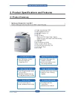
Page 35: ...Service Manual 2 21 Video Controller Power Distribution Product Specifications and Features ...

Page 36: ...and Finisher EXIT STEP MOT BLDC FUSER ROM 1MB SOC Jupiter4E MAIN IF LSU C K LSU P MOTOR LSU Y M HVPS1 CLUTCHS SMPS1 24V COVER OPEN LOWER ACR BASE DUPLEX SCF BLDC BK DEVE CRUM FINISHER WASTE MOT LSU CON HVPS2 CRUM I F ASIC LPEC3 BLDC OPC BLDC DEVE MP ASIC LPEC1 SDRAM 8MB T2 BLDC ITB SMPS3 SIGNAL T1 ENG SENS SMPS2 5V DUPLEX TOP SENS FAN FUSER HUMI COVER OPEN UPPER THERMISTOR EXIT SENS LSU TEMP REGI ...

Page 37: ...Service Manual 2 23 Engine Controller Power Distribution Product Specifications and Features ...

Page 38: ...0MHz Core Frequency A DADF board supports customer to copy Max 100 sheets of documents automatically Also CLX 8380N s DADF is serving up to 65 of Duplex speed And this happens to make one more paper path for high speed paper feeding GATE R_STACK LENGTH DETECT WIDTH DOWNLOAD EXIT MOTOR HYPER DEBUG REGI SENSOR DUPLEX SCAN EXIT SENSOR MAIN I F MPU S3F443FX COVER OPEN SCAN MOTOR SCAN MOTOR DRIVER EXIT...

Page 39: ...Service Manual 2 25 DADF Block Diagram Product Specifications and Features ...

Page 40: ...y_Sub PBAs which are used for scan and fax functions The OP_MAIN PBA includes an ARM based CPU S3C2413C a 32MB NOR Flash ROM a 64MB DDR1 SDRAM memory and a TSP control unit DDR MEMORY 64MB Main IF USB LCD Interface Main IF power OPE Key sub NOR FLASH 32MB JTAG Touch Screen Back Light Unit Debugger OPE Key MCU S3C2413 LCD Interface OPE Key sub NOR FLASH 32MB Product Specifications and Features ...

Page 41: ... 110V 220V power input It has safety protection modes for over current and load SPECIFICATION General Input Output Voltage 1 AC 110V 90V 135V 2 AC 220V 180V 270V 3 Input Current 5 0 Arms 4 Output Power 335W Max 450W DC 5V 45W 60W DC 24V 290W 390W Connection 1 INPUT_AC from Fuser Drive Board 2 OUTPUT_5V1 2 3 to Engine PBA 3 OUTPUT_24V1 2 3 4 to Engine PBA 4 SMPS control from Engine PBA Product Spec...

Page 42: ...round 24V Ground GND 17 18 GND 24V Ground Power 24V4 19 20 24V4 Power Power 24V4 21 22 GND 24V Ground 24V Ground GND 23 24 GND 24V Ground Signal RS24V 25 26 reserved Signal 24V Remote Sense Reserved DC Output Connector CN3 Description PIN NO PIN ASSIGN PIN NO Description Power 5V1 1 2 5V1 Power Power 5V1 3 4 GND 5V Ground 5V Ground GND 5 6 GND 5V Ground Power 5V2 7 8 5V2 Power Power 5V2 9 10 GND 5...

Page 43: ...ltage channels which includes T1 4 T2 MHV 4 DEVE 4 FB and SP HVPS_L High Voltage Power Supply_Large supplies High Voltage power to Drum cartridge Charger ITB T2 roller T2 Unit Connection 1 T1_Y M C K to ITB 2 HVPS_L S connection to HVPS_S 3 HVPS1 from Engine PBA 4 HVPS2 from Engine PBA 5 MHV_AC_Y M to Drum cartridge 6 MHV_AC_C K to Drum cartridge 7 T2 to T2_Unit Product Specifications and Features...

Page 44: ... MΩ 500 V 0 800 V 0 30 uA T1 DC 4 Constant I PWM Duty 90 MΩ 14 uA 0 40 uA 0 3 5 KV T2 DC 1 Constant I PWM Duty 100 MΩ 30 uA 0 50 uA 0 6 5 KV DC Constant V Volume 80 MΩ 1300 V 0 20 uA Saw Plate DC 1 Constant V PWM Duty NO 1000 V 0 2 4 KV 0 40 uA Fuser Bias DC 1 Constant V PWM Duty NO 1000 V 0 1 5 KV 0 20 uA Constant current outputs in T1 T2 channels Individual T1 channels for each color Alternative...

Page 45: ... sends a zero crossing detect signal to the ENGINE PBA The zero crossing output consists an open collector node Connection 1 INLET AC 2 FUSER CONTROL from Main board 3 FUSER AC to Fuser lamp 4 SMPS AC to SMPS Specification V1 V2 Input Voltage Range AC 110V 90 135V AC 220V 180 270V Input Current 20A 10A Output Power Max 1500W Max 1500W Phase Detect Zero Crossing Detect Open Collector Output Protect...

Page 46: ...D Interface Cable Connector 3Ways D Sub 15P Female 10 11 12 13 14 15 FIN_DETECT nFIN_RESET 5V N C 3 3V 24V 24V 24V RxD TxD FIN_DETECT nFIN_RESET 5V N C 3 3V 24V 24V 24V GND 3 3 5V Power GND 3 3 5V Power GND 24V Power GND 24V Power FG Case 1 2 3 4 5 6 7 8 9 1 2 3 4 5 6 7 8 9 10 11 12 13 14 15 Connector 3Ways D Sub 15P Male TTL Level 3 3V GND 24V Power GND 3 3 5V Power GND 3 3 5V Power GND 24V Power...

Page 47: ...ith a Main controller This PBA is also used in HCF Key function is same with SCF and HCF SCF can be able to be composed together No Signal Name Direction Active Level Description 1 24V POWER 24V Power 2 3 3V POWER 3 3V Power 3 GND POWER Signal Ground 4 TxD OUT Data Transmission 5 RxD IN Data Receive 6 nBUSY OUT LOW SCF TxD Line Busy 7 nCMDREQ OUT LOW Command Request 8 Reserved1 I O LOW Reserved 9 ...

Page 48: ...n MMR 33 6Kbps Phase C by ITU T No 1 Chart in Memory transmission with ECM Scan Speed Platen 2 sec A4 ADF 5 5 sec A4 Scan time 2 sec A4 203x98dpi Scan setup time 3 5 sec Receive Mode Fax TEL ANS FAX Compression MH MR MMR JBIG JPEG ECM Yes Resolution Std 203 98dpi Fine 203 196dpi S Fine 203x392dpi 300 300dpi 406x392dpi Contrast Adsustable 5 levels Fax Memory 32MB in HDD Product Specifications and F...

Page 49: ...w to connect a serial fax first 1 connect a line cord into Line RJ11 2 Connect 2 nd phone by 4 line cord How to connect Parallel Fax 1 Connect a line cord into Line RJ11 2 Just connect a phone to External RJ11 Product Specifications and Features ...

Page 50: ...Service Manual 2 36 2 3 2 11 Other PBAs DEVE CRUM PBA Finisher IF PBA ERASER_LAMP_PBA SCAN_IF_PBA Product Specifications and Features ...

Page 51: ...n Exit Paper Size Legal Letter A4 2 SCF Second Cassette Feeder HCF High Capacity Feeder This additionally stores and automatically feeds printing paper Its function is the same as the FCT First Cassette Tray Spec Paper Direction FISO Front in Side Out Cassette Type A4 Ltr Paper Discharge Separation Claw Capacity SCF 500 Sheets Standard paper 75mg m2 20lb HCF 2100 Sheets Standard paper 75mg m2 20lb...

Page 52: ...Magenta Cyan Color DEVE Motor is for Color DEVE Yellow Magenta Cyan Fuser Motor is for Fuser and Exit roller Duplex Motor is for Duplex feeding Exit Motor is for stable stacking Toner Supply Motor is for toner supply Duplex Motor Fuser Motor Exit Motor Duplex Motor Fuser Motor Exit Motor BK Motor Main Motor Color OPC Motor Color DEVE Motor BK Motor Main Motor Color OPC Motor Color DEVE Motor Toner...

Page 53: ...rn on and Polygon motor starts If the receiving part in LSU detect the beam Hsync is generated When the rotation of polygon motor is steady it is time of LSU ready status for printing If either of two condition is not satisfied LSU error is expected OPC Drum Photo Diode LD Driver circit Protector panel LD Laser Diode Polygon Mirror Polygon Motor Motor Driver K C M Y K C M Y K C M Y Product Specifi...

Page 54: ... Device Fuser Bias 700V HH 500V LL NN on the P R tube Thermostat When a heat lamp is overheated a Thermostat cuts off the main power to prevent over heating Non Cotact type Thermostat Heat roller Belt The heat roller Belt transfers the heat from the lamp to apply a heat on the paper The surface of belt is coated with PFA so toner does not stick to the surface Pressure roller A pressure roller moun...

Page 55: ...r Over Heat only N A Less than Stand By Ref Temp 40 For more than 10 seconds Higher than 230 240 For continuous 30 seconds 5 sec StandBy Ref Temp 10 for more than 3 min Printing N A Less than Printing Ref Temp 20 For more than 10 seconds Higher than 220 230 For continuous 20 seconds 3 sec Power Save N A N A Higher than 220 230 For continuous 20 seconds 3 sec StandBy Ref Temp 10 for more than 3 min...

Page 56: ...ween S4L9335X and CIP4 It uses CDS Correlated Double Sampling which implement double Sampling for black level and image by using signal of CIP4E when AFE receives each pixels 3 Image Processor It reads pixel data of CCD Charge Coupled Device by 600dpi Line and in accordance with the mode set from CIP4 said data is experiencing Error Diffusion Algorithm in mode or stored at Scan Buffer through DMA ...

Page 57: ...40cpm LTR duplex 25cpm LTR Document Size Width 148 to 216 mm Length 145 to 356 mm for single page scan 145 to 400 mm for multi pages scan Document Size Sensing Yes Extendible tray for long documents Yes Adjustable Paper Guide Yes DADF Ready Indicator None Labels w graphics None Book copying with DADF open Yes Wear out items rolls easily replaceable w o tools No Wear out items rolls should be servi...

Page 58: ...eature Service Manual 2 44 Layout INDEX Description Qty Remark MOTOR 2 ELECTRONIC CLUTCH 2 SOLENOID 1 PHOTO SENSOR 7 To detect Paper size GATE 2 3 steps GATE 1 Document Path SIMPLEX ⓐ ⓑ ⓒ ⓓ ⓔ DUPLEX ⓐ ⓑ ⓒ ⓕ ⓖ ⓗ ⓒ ⓘ ⓙ ⓚ ⓔ ...

Page 59: ... on Duplex path Cassette Detect Check cassette insertion Paper Limit Check raising paper up to feeding position Paper Low Sensor Check the number of paper below 100 pages MPF Empty Sensor Check paper empty on MPF Power Low Sensor Cassette Detect Paper Empty Sensor MPF Empty Sensor Bin Full Sensor Duplex Jam Duplex Ready Exit Sensor Paper Limit Regi Sensor Power Low Sensor Cassette Detect Paper Emp...

Page 60: ...23 18 19 28 30 3 41 42 43 44 40 24 25 26 29 31 2 14 15 16 4 1 5 20 32 48 51 50 57 56 54 55 46 47 53 52 49 17 6 22 7 8 9 10 12 11 13 45 21 33 34 35 36 37 38 39 40 27 23 18 19 28 30 3 41 42 43 44 40 24 25 26 29 31 2 14 15 16 4 1 5 20 32 48 51 50 57 56 54 55 46 47 53 52 49 Product Specifications and Features ...

Page 61: ...SENS_T1_ENGAGE 23 SENS_T2_ENGAGE 24 SENS_CTD 25 26 SENS_ACD1 2 27 SENS_LSU_CLN 28 INNER_TEMP 29 OUT_TEMP 30 SENS_HUMIDITY 31 WASTE_FULL 32 SENS_WTB_MOT 46 47 AUTO_PAPER_SIZE 2 48 DADF_COVER_OPEN 49 CCD HOME SENSOR 50 SENS_DOC_DUPLEX 51 SENS_DOC_SCAN 52 SENS_DOC_LENGTH 53 SENS_DOC_EXIT 54 SENS_DOC_REGI 55 SENS_DOC_WIDTH 56 SENS_DOC_DETECT 57 SENS_DOC_GATE 58 SENS_GATE_HP 59 SENS_R_STACK 33 34 35 36...

Page 62: ...UNCTION M1 FUSER DRIVE BLDC MOTOR M9 LSU CLEANING DC MOTOR M2 EXIT DRIVE STEPPING MOTOR M10 WASTE TONER BOTTLE DRIVE DC MOTOR M3 DUPLEX DRIVE STEPPING MOTOR M11 T1 ENGAGE DC MOTOR M4 MAIN DRIVE BLDC MOTOR M12 T2 ENGAGE DC MOTOR M5 BLACK OPC DEVE DRIVE BLDC MOTOR F1 FAN DC HVPS M6 COLOR DEVE DRIVE BLDC MOTOR F2 FAN DC INVERTER SMPS M7 COLOR OPC DRIVE BLDC MOTOR F3 FAN DC DUPLEX M8 TONER SUPPLY DRIV...

Page 63: ...nter off and wait until the printer to cool before replacing it To avoid the print quality problems do not touch the surface of rollers transfer roller pick up roller feed roller Cartridge transfer Cleaning Make sure the power cord is unplugged before the cleaning Do not use flammable liquid cleaner or spray products for cleaning Avoid making scratches while cleaning the parts Avoid direct contact...

Page 64: ...l 2 Press Machine Status the Machine Info tab Print Report 3 Select the report type then the right side of the screen shows the list to print 4 Select the list to print 3 1 2 2 Monitoring the supplies life If you want to view the consumables life follow the next step 1 Press the Machine Setup button on control panel 2 Press the Machine Status 3 Scroll down to browse the entire supplies with list v...

Page 65: ... Pages Toner Cartridge Black 20K Pages Imaging Unit Cyan 30K Pages Imaging Unit Magenta 30K Pages Imaging Unit Yellow 30K Pages Imaging Unit Black 30K Pages Waste toner container 48K Images a Declared yield value in accordance with ISO IEC 19798 b Image counts are based on one color on each page If you print documents in full color Yellow Magenta Cyan Black the image count will be added by 4 image...

Page 66: ...it a few minutes for the machine to cool 2 Open the side cover 3 Open the front cover 4 Pull the corresponding toner cartridge out from the machine 5 Remove the new toner cartridge from its bag 6 Thoroughly roll the new cartridge five or six times to distribute the toner evenly inside the cartridge 7 Pull out the protecting film in the cartridges ...

Page 67: ...ait a few minutes for the machine to cool 2 Open the side cover 3 Open the front cover 8 Hold the new toner cartridge by the handle and slide the new toner cartridge in until it locks in place 9 Close the front cover then the side cover 10 Make sure that the cover is securely latched and then turn the machine on ...

Page 68: ...hine using the handle on its bottom 7 Remove the new imaging unit from its bag 8 Remove the paper protecting the surface of the imaging unit 9 Remove the cap and carefully pull the seal tapes out of the imaging unit 10 Thoroughly shake the new imaging unit side to side five or six times 11 Labels inside the machine identify each imaging unit s position Holding the handles on the new imaging unit p...

Page 69: ...push it to make sure that it is firmly seated in place 14 Close the front cover then the side cover 15 Make sure that the cover is securely latched and then turn the machine on 3 1 4 3 Replacing the waste toner container 1 Turn the machine off then wait a few minutes for the machine to cool 2 Open the side cover 3 Open the front cover 4 Pull the waste toner container out of the machine using its h...

Page 70: ...ntainer as shown below and use it to close the waste toner container openings 6 Take a new waste toner container out of its package 7 Insert the new container into position and then push it to make sure that it is firmly seated in place 8 Close the front cover firmly 9 Turn the machine on ...

Page 71: ...e Image CARTRIDGE TRANSFER 100K MEA UNIT TR Transfer roller Assy 100K ELA UNIT FUSER LV ELA UNIT FUSER HV 100K MEA HOLDER ADF RUBBER 50K MEA PICK UP DADF pick up Assy 200K MEA UNIT HOLDER PAD MP tray pad Assy 50K ELA HOU MP PICK UP 200K MEA UNIT Exit Duplex 100K MEA UNIT ROLLER PU Pick up roller 100K ...

Page 72: ... 100K Domestic 220V Cartridge transfer Transfer Roller Fuser unit Guide exit Pick up roller 1 1 1 1 3 100K Export 220V Cartridge transfer Transfer Roller Fuser unit Guide exit Pick up roller 1 1 1 1 3 100K Export 110V 3 1 6 Location of Maintenance parts Cartridge transfer Transfer Roller Fuser unit DADF Pick up roller DADF rubber Pad MP tray rubber pad MP tray feed roller Pick up roller ...

Page 73: ...embly Service Manual 3 11 3 1 7 Replacing the Maintenance parts 3 1 7 1 How to replace the Cartridge transfer 1 Open the front and side cover 2 Take out the cartridge 3 Take out the Cartridge transfer and replace the new one ...

Page 74: ...3 How to replace the Fuser unit 1 Open the side cover and then pull the guide paper up in the direction of arrow 2 Push the latch in the two directions and pull the Transfer roller And replace the new one 1 Open the side cover 2 Pull the Fuser unit by holding the green lever And replace the new one ...

Page 75: ...assembly Service Manual 3 13 3 1 7 4 How to replace the DADF pick up roller and rubber pad 1 Open the DADF Cover 2 Pull the bush in the direction of arrow Then lift the DADF pick up roller out 3 Remove the rubber pad unit ...

Page 76: ...p Roller To remove the pick up roller first take out the cassette After remove the cassette you can see the pick up roller in the inner Pull the lever of pick up roller in the direction of arrow Roller Pick Up Roller Forward Roller Retard Roller Pick Up Roller Forward Roller Retard ...

Page 77: ...2 2 general disassembly procedure 3 Remove the 4 screws and 2 hooks and take out the MP Assy 1 Remove the 1 screw Remove the Bracket and Gear as shown below 2 Remove the MP pad unit after remove the 1 screw Bracket Gear Bracket Gear Hook Left Right Hook Hook Hook Left Right Bracket Gear Bracket Gear Hook Left Right Hook Hook Hook Left Right Bracket Gear Bracket Gear Hook Left Right Hook Hook Hook ...

Page 78: ...ove the 4 screws from both side of MP unit 8 Lift up the FRAME MP TOP ELA HOU MP MEA UNIT HOLDER PAD ELA HOU MP MEA UNIT HOLDER PAD ELA HOU MP MEA UNIT HOLDER PAD ELA HOU MP MEA UNIT HOLDER PAD ELA HOU MP MEA UNIT HOLDER PAD ELA HOU MP MEA UNIT HOLDER PAD ELA HOU MP MEA UNIT HOLDER PAD ELA HOU MP MEA UNIT HOLDER PAD ELA HOU MP MEA UNIT HOLDER PAD ELA HOU MP MEA UNIT HOLDER PAD ...

Page 79: ... LOWER 11 Replace the ELA HOU MP PICK UP with new one How to reassemble MP feed roller 12 Assemble the spring to ELA HOU MP Pick up 13 Fix the LATCH ARM F R ELA HOU MP PICK UP ELA HOU MP PICK UP ELA HOU MP PICK UP ELA HOU MP PICK UP ELA HOU MP PICK UP ELA HOU MP PICK UP ELA HOU MP PICK UP ELA HOU MP PICK UP ...

Page 80: ...vice Manual 3 18 14 When reassembling the FRAME MP TOP assemble the STOPPER PAPER F R to be in the hole 15 Check that LATCH ARM F R assemble properly 16 Assemble the SPRING as shown below 17 Assemble in reverse order after this step ...

Page 81: ...f arrow And Release the damper unit securing the both side of the Side duplex cover 1 2 Damper unit 1 2 Damper unit 1 2 1 2 Damper unit 1 2 Damper unit 1 2 Damper unit 1 2 1 2 Damper unit 3 1 7 7 How to replace the MEA UNIT Exit Duplex Before MEA UNIT Exit Duplex disassembly you must remove the covers Deve drive unit refer to 3 2 2 general disassembly procedure ...

Page 82: ...sassembly Service Manual 3 20 3 Remove the Side Duplex cover 4 Release the Exit Duplex Unit by removing the 4 hooks after remove 1 screw MEA UNIT EXIT DUPLEX MEA UNIT EXIT DUPLEX MEA UNIT EXIT DUPLEX MEA UNIT EXIT DUPLEX ...

Page 83: ...cement consumable Toner Cartridges Imaging Units WTB When displayed Toner Empty or Replace Drum or Waste Toner Full Cleaning of Feed frame and Feed Rollers on the paper path Misfeeds or Jams occur frequently Cleaning of Document Platen glass The same copy area is dirty whenever making copies Original cannot be cleanly scanned Cleaning of Platen Cover sheet sponge Cleaning Feeder and PAD in the DAD...

Page 84: ...d on the figure below 2 Cleaning Transfer Roller Cleaning Kit Vacuum Cleaner and Dry rag or Soft cloth Mal Affects Dust particles from paper can be copied at worst making spot stains on the paper When exchanging the Transfer Roller clean the area Follow the display listed on the figure below 3 Cleaning Frame Inside Cleaning Kit Vacuum Cleaner and Dry rag or Soft cloth Mal Affects The toner can lea...

Page 85: ... out the cartridge Take out the Cartridge Transfer Cover with a piece of paper and lay it on a flat surface Clean the paper path parts Clean the paper path parts Release the transfer roller Clean the paper path parts 1 2 3 1 1 2 3 3 4 6 4 4 6 6 7 9 8 7 7 9 9 8 8 5 5 5 ...

Page 86: ...arts Clean the transfer roller unit parts Clean the Frame inside Reassemble the Cartridge Transfer Reassemble the cartridge Reassemble the transfer roller Clean the transfer roller unit parts Clean the transfer roller unit parts 10 11 12 10 10 11 11 12 12 13 13 14 14 15 16 16 17 17 ...

Page 87: ...e you must perform as follows 1 Check to verify that documents are not stored in memory 2 Be sure to remove the toner cartridge before you disassemble parts 3 Unplug the power cord 4 Use a flat and clean surface 5 Replace only with authorized components 6 Do not force plastic material components 7 Make sure all components are in their proper position Releasing Plastic Latches Many of the parts are...

Page 88: ...CH18A 1 6003 001256 SCREW TAPTITE BH B M4 L10 NI PLT SWRCH18A 7 6009 001396 SCREW SPECIAL PH M3 L10 3 ZPC BLK SWRCH18A B TITE 2 6003 000282 ELA UNIT SIZE SENSOR SCREW TAPTITE BH B M3 L8 ZPC BLK SWRCH18A 2 6003 000266 ELA UNIT CST SENSOR SCREW TAPTITE PWH S M3 L6 ZPC WHT SWRCH18A 2 6003 000269 ELA UNIT BASE PLATE R SCREW TAPTITE BH S M3 L6 ZPC WHT SWRCH18A 13 6003 001474 SCREW TAPTITE BH B M3 L30 Z...

Page 89: ... L10 NI PLT SWRCH18A 2 6003 000196 MEA UNIT DUMMY UPPER SCREW TAPTITE PWH B M3 L10 NI PLT SWRCH18A 1 6003 000196 ELA HOU DADF SCREW TAPTITE PWH B M3 L10 NI PLT SWRCH18A 7 6003 000269 SCREW TAPTITE BH S M3 L6 ZPC WHT SWRCH18A 8 6003 001256 SCREW TAPTITE BH B M4 L10 NI PLT SWRCH18A 5 6003 000196 ELA HOU COVER PLATEN SCREW TAPTITE PWH B M3 L10 NI PLT SWRCH18A 14 6003 001324 SCREW TAPTITE BH B M4 L16 ...

Page 90: ...S SCREW TAPTITE PWH B M3 L10 NI PLT SWRCH18A 2 6003 000269 ELA UNIT SUPPORT REAR SCREW TAPTITE BH S M3 L6 ZPC WHT SWRCH18A 2 6003 000282 CARTRIDGE DRUM Y KIT SCREW TAPTITE BH B M3 L8 ZPC BLK SWRCH18A 7 6001 000130 ELA HOU DEVE UNIT SCREW MACHINE BH M3 L6 ZPC WHT SWRCH18A 2 6003 000282 SCREW TAPTITE BH B M3 L8 ZPC BLK SWRCH18A 5 6006 001193 SCREW MACHINE PH WSP M3 10 ZPC WHT SWRCH18 A WD8 TEMPERED ...

Page 91: ...3 000196 ELA HOU OPE SCREW TAPTITE PWH B M3 L10 NI PLT SWRCH18A 10 6003 000269 SCREW TAPTITE BH S M3 L6 ZPC WHT SWRCH18A 4 6003 000196 ELA HOU OPE COVER SCREW TAPTITE PWH B M3 L10 NI PLT SWRCH18A 7 6002 000440 ELA UNIT FUSER LV SCREW TAPPING PWH 2 M3 L8 ZPC BLK SWRCH18A 3 6003 000196 SCREW TAPTITE PWH B M3 L10 NI PLT SWRCH18A 17 6003 000269 SCREW TAPTITE BH S M3 L6 ZPC WHT SWRCH18A 9 6003 001086 S...

Page 92: ...MFP 4 Remove the Cover rear and the Cover rear lower 5 Remove the 2 screws and then remove the Unit Cover Top M3X10 M4X10 M3X10 M4X10 M3X10 M4X10 M3X10 M4X10 M3X10 M4X10 M3X10 M4X10 M3X10 M4X10 M3X10 M4X10 M3X10 M4X10 M3X10 M4X10 M3X10 M4X10 M3X10 M4X10 M3X10 M4X10 M3X10 M4X10 M3X10 M4X10 M3X10 M4X10 M3X10 M4X10 M3X10 M4X10 M3X10 M4X10 M3X10 M4X10 Note In case of being installed the fax kit remove...

Page 93: ...cover 3 2 2 2 DADF 1 Remove one screw and disassemble the cover 2 Unplug the cable and lift up the DADF from the SET in the direction of arrow 3 Open the DADF cover and remove the one screw 4 Lift up the stacker and remove the two screws SIDE DUPLEX COVER COVER FRONT COVER SIDE LEFT SIDE DUPLEX COVER COVER FRONT COVER SIDE LEFT ...

Page 94: ...er of the DADF 6 Unplug the all harness from the DADF board 7 Remove the 2 screws and then remove the harness holder 8 Remove the 3 screws and then remove the DADF board 9 Pull the bush in the direction of arrow Then lift the DADF pick up roller out 10 Remove the DADF pad unit ...

Page 95: ...screws 2 Lift up the OPE assy as shown below and Unplug the connector And release the OPE assy from set 3 Disconnect the 2 harness 3 flexible pcb and remove the 4 screws And then remove the OPE PBA 4 To remove the LCD panel remove the 10 screws Take out the LCD panel after remove the LCD panel shield ...

Page 96: ...Front dummy cover and release it 2 Remove the 4 screws from front down side of scan assy 3 Remove the 3 screws and all harness connected to scan assy 4 Lift up and release the Scan Assy 5 Release the Scan upper from the Scan lower after remove the 6 screws cap hole screw 3 EA 1 2 3 1 2 3 1 2 3 1 2 3 ...

Page 97: ...e scan upper after remove the 2 screws 7 To remove the CCD harness first remove the sheet 8 Unplug the FFC cable and power cable 9 Remove the CCDM after remove the CCDM belt 10 Remove the Scan motor assy after remove the 4 screws 11 To remove the CCD harness remove the sheet 2 2 2 2 ...

Page 98: ...cing the Belt compress the spring 3 2 2 5 Engine and Video controller 1 Unplug the all harness and remove the 4 screws from Video controller And release it Caution When reassembling be careful the screw type 2 Unplug the all harness and remove the 9 screws from Engine controller And release it M3X10 S3X6 M3X10 S3X6 ...

Page 99: ...7 3 2 2 6 SMPS and Fuser Drive board 1 Remove the 3 screws and 1 connector Remove the SMPS cover 2 Unplug the all harness and remove the 4 screws from FDB And release it 3 Remove the all harness from SMPS 4 Remove the SMPS after remove the 8 screws ...

Page 100: ...ove the SMPS cover 2 Release the harness from the harness holder 3 Remove the engine controller shield after remove the 5 screws Caution When reassembling be careful the screw type 4 First remove the 4 fixer and remove the 2 screws Release the part as shown below fixer fixer fixer M3X10 S3X6 M3X10 S3X6 ...

Page 101: ...n the direction of arrow Note When disassembling the main drive unit Don t have to unplug the cluthc harness If you want to replace the clutches refer to the next page 6 Remove the Main drive Unit after remove the 6 screws fixer fixer fixer M3X10 S3X6 M3X10 S3X6 ELA UNIT DRIVE MAIN ELA UNIT DRIVE MAIN ...

Page 102: ...t grip with force It is easy to disconnect 2 Unplug the harness as shown below 1 When reassembling the 2 clutch below check the harness color There is the incuse on the shield B B means black black harness G B means gary black harness 2 When reassembing the cluches check the cluch color The top clutch color is white Others are black ...

Page 103: ...l 3 41 3 2 2 8 Deve Drive Unit 3 2 2 9 Fuser Drive Unit 1 Release the harness holder in the direction of arrow after remove the 2 screws 2 Remove the 6 screws and remove the Deve Drive unit 1 Remove the 6 screws and remove the Fuser Drive unit ...

Page 104: ...1 Remove the left side cover Refer to 3 2 Cover Unplug the all connector from HVPS L Remove the HVPS L after remove the 9 screws 3 Unplug the all connector from HVPS S Remove the HVPS S after remove the 5 screws 2 Remove the HVPS holder and FAN after remove the 3 screws ...

Page 105: ... Manual 3 43 3 2 2 11 LSU 1 To remove the LSU unit first remove the left side cover and HVPS board Remove the all connector as shown below And remove the LSU pusher unit after remove the one screws 2 Take out the LSU unit LSU LSU LSU LSU ...

Page 106: ...Maintenance and Disassembly Service Manual 3 44 ...

Page 107: ...ent Troubleshooting This chapter describes some of the main service procedures including Clearing paper jams Using the Diagnostic modes How to upgrade the firmware Troubleshooting Duplex Pass MP Feed Cassette Feed Finisher Pass Simplex Pass Duplex Pass MP Feed Cassette Feed Finisher Pass Simplex Pass ...

Page 108: ...r metal tools when clearing a paper jam This could damage the internal mechanism causing print quality problems or possibly electrical shock JAM type Standard tray LSU Unit Scanner Unit Cartridge Transfer Unit Duplex Unit Jam 0 Jam 1 Jam 2 Duplex Jam 1 Toner bottle Unit Cartridge Drum Unit DADF Unit Standard tray LSU Unit Scanner Unit Cartridge Transfer Unit Duplex Unit Jam 0 Jam 1 Jam 2 Duplex Ja...

Page 109: ...gistration Cartridge Transfer Cartridge Transfer Fuser Exit Duplex Exit Duplex Jam 1 Roller Regi Guide exit Duplex Guide exit Duplex Jam 2 Trailing edge of media does not leave Exit Sensor within a certain time after touching registration 1 Open side cover 2 Remove jammed paper OR 1 Remove jammed paper from exit Pick Up Registration MP Feed Registration Cartridge Transfer Cartridge Transfer Fuser ...

Page 110: ...m the tray while your machine is printing Flex fan and straighten paper before loading Do not use creased damp or highly curled paper Do not mix paper types in a tray Use only recommended print media Ensure that the recommended side of the print media is facing up in the tray or facing down in the multi purpose tray If paper jams occur frequently when you print on A5 B5 sized paper Load the paper ...

Page 111: ...ADF 2 Open the DADF cover 3 Gently remove the jammed paper from the DADF 4 Close the DADF cover Then reload the pages you removed if any in the DADF Misfeed of exiting paper 1 Remove the remaining documents from the DADF 2 Open the DADF cover 3 Open the document input tray upwards and pull the document gently out of the DADF 4 Close the DADF cover and the document input tray Then place the documen...

Page 112: ...by carefully pulling it to the right using both hands if you do not see the paper in this area stop and go to step 3 3 Open the white document background 4 Remove the paper from the feed area by carefully pulling 5 Close the white document background and the scanner lid Then load the removed pages back into the DADF 1 scanner lid 1 1 scanner lid 1 ...

Page 113: ...tray 2 HCF Paper Jam in tray3 Paper Jam in MP tray In the paper feed area tray 1 optional tray or multi purpose tray Paper Jam in exit area In the paper inside the machine Paper Jam inside of machine In the fuser area Paper Jam at the bottom of duplex path Paper Jam at the top of duplex path Paper Jam inside of duplex path In the duplex unit Paper jam in front of finisher Paper jammed in the stack...

Page 114: ... front part of the tray up slightly to release the tray from the machine 5 Remove the jammed paper by gently pulling it straight out Once you remove the jammed paper here open the side cover and then close it to clear the error message on the display 6 Close the side cover and insert the paper tray Lower the rear part of the Tray to align the rear edge with the corresponding slot of the machine th...

Page 115: ...f the paper does not move when you pull or if you do not see any paper in this area stop and go to step 4 4 Lift the front part of the tray slightly up to release the tray from the machine If the paper does not move when you pull or if you do not see the paper in this area stop and go to step 3 5 Remove the paper in the direction shown To avoid tearing the paper pull it out gently and slowly 6 Ins...

Page 116: ...igh capacity feeder 3 Pull the jammed paper out in the direction shown pulling gently and slowly in order to avoid tearing the paper If the paper does not move when you pull or if you do not see any paper in this area stop and go to step 4 4 Pull out the optional high capacity feeder 5 Lift the front part of the tray slightly up to release the tray from the machine ...

Page 117: ...void tearing the paper If the jammed paper is not visible or if the paper is stuck stop pulling and continue on to step 5 7 Insert the paper tray and close the two covers In the multi purpose tray 1 If the paper is not feeding properly pull the paper out of the machine 2 Open and close the side cover Printing automatically resumes ...

Page 118: ...chine 1 Open the side cover 2 Remove the jammed paper in the direction shown If you do not see any paper in this area go to step 3 3 Open the guide in the direction shown and pull the jammed paper gently out of the machine 4 Open and close the front cover to resume printing ...

Page 119: ...on shown 3 Close the side cover Printing automatically resumes In the duplex unit area If the duplex unit is not inserted correctly paper jam may occur Make sure that the duplex unit is inserted correctly 1 Open the side cover 2 Release the guide to pull the jammed paper easily 3 Remove the jammed paper 4 Close the side cover ...

Page 120: ...c lever and then push stacker to left 3 Remove the jammed paper 4 Slide in the stacker until you hear the sound click 5 Close the stacker front cover Paper jam inside finisher Paper jam inside finisher s duplex 1 Open the stacker front cover 2 Pull the stacker lever 1a down If necessary pull the stacker lever 1b down as well 3 Remove the jammed paper ...

Page 121: ...ual 4 15 4 Pull up on the stacker lever and then close the stacker front cover Paper jam at exit of finisher 1 Gently pull the paper out through the exit area 2 Close the side cover Printing automatically resumes 3 Remove the jammed paper ...

Page 122: ... Unit 2 T2 Roller 88 0 White and Black Spot Periodic Banding Rear Side Paper Dirty Transfer Roller 3 Registration Roller 59 7 Roll Mark 4 Pick up Roller 72 3 Roll Mark 5 Drive Roller 77 8 Periodic Banding Color Registration ITB Unit 6 T1 Roller 44 0 White and Black Spot Periodic Banding ITB Unit 7 Exit Roller 47 1 Roll Mark Vertical Scratch 8 OPC Drum 94 3 White and Black Spot Periodic Banding Gho...

Page 123: ...k page Print this page Align the this page and the printed defect image and find the defective roller Pressure roller T2 roller Regi roller Registration Roller Pick up roller Drive roller T1 roller Exit roller OPC Drum Start line Charge roller Magnetic roller CMYK Fuser belt ...

Page 124: ...e Manual 4 18 No Description No Description 1 ROLLER PRESSURE 6 ROLLER TRANSFER 2 ROLLER TRANSFER 7 Exit roller 3 ROLLER REGIDLE 8 Cartridge Drum unit 4 RUBBER ROLLER PU 9 Fuser belt 5 ROLLER DRIVE 1 4 3 2 5 6 7 8 9 1 4 3 2 5 6 7 8 9 ...

Page 125: ...ng the current job that the user can stop or resume 13 Start Starts a job 1 Machine Setup Leads you to the machine setup and advanced settings 2 Job Status Shows the jobs currently running queued jobs or completed jobs 3 Status Shows the status of your machine 4 Display screen Displays the current machine status and prompts during an operation You can set menus easily using the touch screen 5 Nume...

Page 126: ...s amount of toner used LCD Brightness Adjusts the brightness of the touch screen You can change the display language Guides you to remove the USB memory devices from the machine Follow the instruction on the LCD This icon appears only when you connect an USB memory module Logout Logs out from the currently logged in account Machine Setup button When you press Machine Setup button you can browse cu...

Page 127: ... All Removes all the jobs from the list Close Closes the job status window and switches to previous view Power Saver button When the machine is not in use save electricity with the provided power save mode Pressing this button puts the machine into power save mode If you press Power Saver button for more than two seconds a window appears requesting that you turn the power off If you choose Yes the...

Page 128: ... On The imaging unit is totally out of lifespan Remove the old imaging unit and install a new one The toner cartridge is totally empty Remove the old toner cartridge and install a new one A paper jam has occurred The cover is opened Close the cover There is no paper in the tray Load paper in the tray The machine has stopped due to a major error Check the display message The waste toner container n...

Page 129: ...t Original Type Darkness Paper Supply Advanced tab ID Copy N Up Poster Copy Clone Copy Book Copy Booklet Covers Transparencies Image tab Erase Edge Erase Background Margin Shift Fax Optional Basic tab Address Duplex Resolution Advanced tab Original Size Delay Send Priority Send Polling Mailbox Image tab Original Type Darkness Erase Background Color Mode Scan Scan to Email Basic tab Advanced tab Im...

Page 130: ...e Details Customer Support Machine Serial Number Hardware Options Configuration Software Versions Tray Status Tray Status Paper Size Paper Type Print Report System Report Scan Report Fax Report Usage Counters Total Impressions Black Impressions Black Copied Impressions Black Printed Impressions Color Impressions Color Copied Impressions Color Printed Impressions Sheets Copied Sheets Copied Sheets ...

Page 131: ...b Copy Setup Fax Setup Network Setup Authentication Optional Service Color Print Report tab Print Accounting Reports Report Current Job tab Detail Delete Delete All Close Active Notice tab Detail Close Completed Job tab Detail Close s s s nt s General tab Device Info Date Time Default Settings Measurement Timers Language Power Saver Tray Management Altitude Adjustment Output Options Contention Man...

Page 132: ...r Output Selects Collated or Uncollated copy options If you install the optional stacker stapler then the staple related option appears Text Text Photo Photo Magazine Improves the copy quality by selecting the document type for the current copy job Color B W You can switch this copy mode between Color mode and B W mode Selects whether the user print copies in mono or color Light Dark Adjusts the b...

Page 133: ...page Book Copy Allows you to copy an entire book Booklet Creates booklets from a sequential set of either 1 sided or 2 sided originals Covers Automatically adds covers to your copied set using stock taken from a different tray Transparencies Adds a blank or printed divider between transparencies within a set Image Tab Erase Edge Allows you to erase punch holes staple marks and fold creases along a...

Page 134: ...one side of the original both sides of the original Resolution Adjusts the resolution options Advanced Tab Original Size Selects the size of the original document Press OK to update current setting Delay Send Sets the machine to send a fax at a later time without your intervention Priority Send Sends an urgent fax before reserved operations Polling Used when the receiver requests the document to b...

Page 135: ...message asking Auth ID and Password it means the network administrator has set the authentication in SyncThru Web Service Press Scan to Email NetScan or Scan to Server Scan to Email Scans and sends the scanned output to the destination by email NetScan Scans and sends the scanned output to the destination with the Network Scan Manager program Scan to Server Scans and sends the scanned output to th...

Page 136: ...il addresses from your computer using the SyncThru Web Service Duplex Selects whether the machine scans on one side of the paper 1 Sided both sides of the paper 2 Sided or both sides of paper but back is rotated 180 degrees 2 Sided Rotate Side 2 Resolution Selects the scanning resolution value Back Returns to the previous screen If the network authentication is enabled the log off confirmation mes...

Page 137: ...es of the paper 2 Sided or both sides of paper but back is rotated 180 degrees 2 Sided Rotate Side 2 Resolution Selects the scanning resolution value Back Returns to the previous screen Quality Adjusts the display quality of the scan output File Format Selects the file format of the scan output Scan Preset Automatically changes some scan options such as file format resolution and more You can adju...

Page 138: ...scan output Use left right arrow to adjust the values Erase Background Erases backgrounds like paper patterns Scan to Edge Scans originals from edge to edge Back Returns to the previous screen Output tab Quality Adjusts the display quality of the scan output File Format Selects the file format of the scan output Scan Preset Automatically changes some scan options such as file format resolution and...

Page 139: ...s the separate message showing the basic job information with the file size the paper size and the paper type as well Edit Lets you to modify the file name Delete Deletes the selected list Delete All Deletes all the list Print Prints the selected list 4 1 6 6 Understanding the USB screen When USB memory is inserted into the USB memory port on your machine USB icon shows on the display USB Format Y...

Page 140: ...grade 4 1 7 1 Using the common method Download the firmware file in the temporary folder And unzip the file Delete all current jobs from Job Status window Connect USB cable in the machine idle state Send firmware file hd by usblist2 Drag the f w file and Drop down on the usbprn2 exe And then f w update will be started automatically Please wait until end reboot Drag and Drop ...

Page 141: ...Start menu Programs Network Printer Utilities SyncThru Web Admin Service Firmware Upgrade Upgrade check device using IP address Maintenance Firmware upload register firmware Maintenance Firmware Upload upload firmware 1 2 3 1 2 3 1 2 3 1 2 3 1 2 3 4 1 2 3 4 1 2 3 1 2 3 1 2 3 1 2 3 1 2 3 4 1 2 3 4 1 2 3 1 2 3 1 2 3 1 2 3 1 2 3 4 1 2 3 4 ...

Page 142: ...e Firmware Upload confirm uploaded firmware Maintenance Firmware Upgrade Upgrade choose firmware Maintenance Firmware Upgrade Upgrade choose firmware 1 2 3 1 2 3 1 2 3 1 2 3 1 2 3 1 2 3 1 2 3 1 2 3 1 2 3 1 2 3 1 2 3 1 2 3 1 2 3 1 2 3 1 2 3 1 2 3 1 2 3 1 2 3 ...

Page 143: ...Alignment Troubleshooting Service Manual 4 37 Maintenance Firmware Upgrade Upgrade Maintenance Firmware Upgrade Upgrade Done 1 2 3 4 1 2 3 4 1 2 3 1 2 3 1 2 3 4 1 2 3 4 1 2 3 1 2 3 ...

Page 144: ... window image is not fixed image from the specification point of view Acquire detail information from script Window image is just example image will be implemented 4 1 8 2 How to enter diagnostics mode 1 Press 3 4 key 1 2 3 simultaneously 2 Enter password 1 9 3 4 3 Press OK button 4 1 8 3 How to exit diagnostics mode By pressing the Home button exit Diagnostics mode When exit Diagnostics mode a po...

Page 145: ...ters Fault History Fault Log Fault Counters Test Rountines Copier NVM Read Write NVM Initialization Engine DADF Routines Fax NVM Read Write NVM Initialization Fax Routines Protocol Report Network NVM Initialization Other Print Test Pattern Shading Test Scan Edge Test Memory Clear Print Report Reset Admin Password Test Rountines Copier NVM Read Write NVM Initialization Engine DADF Routines Fax NVM ...

Page 146: ...cs Information General When user selects General OP displays Machine Serial Number Network IP Address and Images since last call HFSI High Frequency Service Items Diagnostics Information HFSI When user selects General OP displays the list of HFSI High Frequency Service Items read from the MCB In the list there are Item Status Actual and Max Life ...

Page 147: ...k Actual counter is bigger than threshold value but smaller than Max Life Off Actual counter exceeds Max Life Negative There is no counter to display In this case it shall display in the Status and Max Life column Actual Values in this column are actual counts for HFSI usage Max Life Values in this column are maximum life limits set for HFSI Reset This button is used to reset the actual counter af...

Page 148: ... are not supported and shall generate an invalid entry message if selected The hard keypad characters of c shall delete all characters displayed within the selected data field By selecting Cancel window moves back to HSFI window without saving user s setting By selecting OK button window moves back to HSFI window saving user s setting Threshold value shall not be greater than Maximum Life Software...

Page 149: ... Printed Sheets Color Printed Sheets 2 Sided Sheets Copied 2 Sided Sheets Black Copied 2 Sided Sheets Color Copied 2 Sided Sheets Printed 2 Sided Sheets Black Printed 2 Sided Sheets Color Printed 2 Sided Sheets Fax Images Received Images Sent Server Fax Images Sent Network Scanning Images Sent Email Images Sent Maintenance Impressions Black Maintenance Impressions Known Jams in the IOT Known Jams ...

Page 150: ...or information occurred Fault Log Diagnostics Fault History Fault Log Fault log window shall display errors occurred while the product was operating Diagnostics Fault History Fault Log Clear When selecting Clear button Pop up will be displayed If you want to delete the Fault history touch the OK button ...

Page 151: ...one item in the list at a time and multiple selection shall not supported User can select Non Zero or All By default Non Zero shall be selected When press OK Fault Counters Detail Window shall be displayed 01 Feeder 02 Fuser 03 Motor Fan 04 LSU 05 Option Interface 06 CRU 07 Finisher 08 DADF 09 FDI 10 Controller 11 Scanner 12 Mismatch Type 13 Network 14 Cloning 18 Memory State 21 Tray 24 MSOK ...

Page 152: ...code is upward 4 1 8 7 Test Routines Tab 4 1 8 7 a Copier NVM Read Write Diagnostics Test Routines Copier NVM Read Write Edit button shall be disabled until any NVM item is selected Edit button shall be disabled when read only NVM is selected Search edit box has 00 000 as a default User shall input the whole number to find a specific NVM by pressing Find button Refer to NVM Read Write table If mat...

Page 153: ...otor 101 Engine Clutch Actuator 102 Engine Paper Handling 103 Engine Timing 104 Engine Consumables 105 Engine Charger 106 Engine Developer 107 Engine Transfer 108 Engine Environment 109 Engine Fixing 110 Engine LSU 111 Engine Toner 112 Engine ACR 113 Engine Option Finisher 114 Engine Option SCF 115 Engine Option Reserved 116 Engine Option Reserved 117 Engine CTD 118 255 Reserved ...

Page 154: ...0020 MHV DC Cyan Charger HV Cyan DC Duty 105 0030 MHV DC Black Charger HV Black DC Duty 105 0040 MHV DC Low Yellow Charger HV Yellow Low DC Duty 105 0050 MHV DC Low Magenta Charger HV Magenta Low DC Duty 105 0060 MHV DC Low Cyan Charger HV Cyan Low DC Duty 105 0070 MHV DC Low Black Charger HV Black Low DC Duty 105 0080 MHV VPP Yellow Charger HV Yellow VPP Duty 105 0090 MHV VPP Magenta Charger HV M...

Page 155: ...er Light Level Value in PWM at Half Speed 110 0040 LD Power Yellow Yellow LD Power at Normal Speed 110 0050 LD Power Magenta Magenta LD Power at Normal Speed 110 0060 LD Power Cyan Cyan LD Power at Normal Speed 110 0070 LD Power Black Black LD Power at Normal Speed 111 0000 Toner Vcon Yellow Toner Vcon Yellow 111 0010 Toner Vcon Magenta Toner Vcon Magenta 111 0020 Toner Vcon Cyan Toner Vcon Cyan 1...

Page 156: ...an Image Area Width for Cyan 112 0230 Manual Color Regi Width Black Image Area Width for Black 117 0000 Total Condition On Off for CTD All Condition of CTD On Off 117 0010 New Crum Condition On Off for CTD The Condition for New Crum of CTD On Off 117 0020 Page Count Condition On Off for CTD The Condition for Page Count of CTD On Off 117 0030 Page Count for CTD Full Page Count for CTD Full 117 0040...

Page 157: ...ms is selected and Initialize button shall be disabled There shall be Back button Diagnostics Test Routines Copier NVM Initialization Initialize If you want to initialize the NVM values press OK button When press OK button SR shall show the initialization progress status and result When the result is get pop up window shall be disappeared ...

Page 158: ...tion is 3 Reset will deselect all selected test routines User select test routine by touching the row and deselect touching it again User input chain number in search edit box and only all test routines in the chain shall be displayed By default Start Stop Stop All shall be disabled Start button shall be enabled when selected item is not running Multiple selection shall not be supported Stop shall...

Page 159: ... Displayed Name Meaning State Displayed 100 0000 Main BLDC Motor Main BLDC Motor is On Off On Off 100 0001 Main BLDC Motor Ready Detect if Main BLDC Motor runs at normal speed High Low 100 0002 Black OPC DEV Motor Black OPC DEV BLDC Motor is On Off On Off 100 0003 Black OPC DEV Motor Ready Detect if Black OPC DEV BLDC Motor runs at normal speed High Low 100 0004 Color OPC Motor Color OPC BLDC Moto...

Page 160: ...Motor Waste Toner Motor On Off On Off 100 0025 Waste Toner Full Sensor Detect if the waste toner is full or not High Low 100 0026 SMPS Fan Run Start Stop Deve Fan run On Off 101 0000 Bypass Feed Clutch Engages drive to pick up a paper from bypass Tray MP Tray On Off 101 0001 T1 Pick Up Clutch Engages drive to pick up a paper from tray1 On Off 101 0002 T2 Pick Up Clutch Engages drive to pick up a p...

Page 161: ...02 0010 T2 Size2 sensor Detects whether auto size2 sensor of tray2 is high or low High low 102 0011 T2 Size3 sensor Detects whether auto size3 sensor of tray2 is high or low High low 102 0012 T2 Stack Height Sensor Detects if paper in tray2 is elevated to the sensor High low 102 0013 T2 Paper Low Sensor Detects when the stack height of tray2 is less than 25 High low 102 0014 Tray3 Home Position De...

Page 162: ...er On Off 105 0006 Cyan MHV Bias Read Cyan Detect what the MHV value is on the MHV Roller On Off 105 0007 Black MHV Bias Read Black Detect what the MHV value is on the MHV Roller On Off 106 0000 Yellow Dev Bias Yellow Dev bias voltage on at normal drive level On Off 106 0001 Magenta Dev Bias Magenta Dev bias voltage on at normal drive level On Off 106 0002 Cyan Dev Bias Cyan Dev bias voltage on at...

Page 163: ... LSU Motor1 On Off On Off 110 0007 LSU Motor2 Run LSU Motor2 On Off On Off 110 0008 LSU LD Power1 LSU LD1 Power On Off yellow On Off 110 0009 LSU LD Power2 LSU LD2 Power On Off magenta On Off 110 0010 LSU LD Power3 LSU LD3 Power On Off cyan On Off 110 0011 LSU LD Power4 LSU LD4 Power On Off black On Off 110 0012 LSU Fan1 Run Start Stop LSU Fan Run On Off 110 0013 LSU Fan2 Run Start Stop LSU Sub Fa...

Page 164: ...t Front Jog Home position High Low 113 0018 Rear Jog Home Sensor Detect Rear Jog Home position High Low 113 0019 Support Finger Home Sensor Detect Support Finger Home position High Low 113 0020 Ejector Home Sensor Detect Ejector Home position High Low 113 0021 Ejector Encoder Sensor Detect Ejector Encoder sensor High Low 113 0022 Stacker Top Sensor Detect Stacker Top position High Low 113 0023 Sta...

Page 165: ...Alignment Troubleshooting Service Manual 4 59 4 1 8 7 b Fax NVM Read Write Diagnostics Test Routines Fax NVM Read Write For the behavior refer to Copier NVM Read Write ...

Page 166: ...Manual 4 60 For the behavior refer to Copier NVM Read Write Edit NVM Initialization Diagnostics Test Routines Fax NVM Initialization By default none of items is selected and Initialize button shall be disabled There shall be Back button ...

Page 167: ...values press OK button When press OK button SR shall show the initialization progress status and result When the result is get pop up window shall be disappeared Protocol Report Diagnostics Test Routines Fax Protocol Report When selecting Protocol Report the sub item will be displayed By pressing the print you can print the protocol report ...

Page 168: ...ting Service Manual 4 62 Fax Routines Diagnostics Test Routines Fax Fax Routines For the behavior refer to Engine DADF Test Routines 4 1 8 7 c Network NVM Initialization Diagnostics Test Routines Network NVM Initialization ...

Page 169: ...stics Test Routines Network NVM Initialization Initialize If you want to initialize the NVM values press OK button When press OK button SR shall show the initialization progress status and result When the result is get pop up window shall be disappeared ...

Page 170: ...iagnostics Test Routines Other Print Test Pattern You can print the test pattern by pressing the start test button By default Test Pattern number shall be 1 You can select paper source by selecting tray of the image You can select simplex duplex printing option by selecting 1 sided 2 sided button ...

Page 171: ...Shading Test The function is used to set the optimum scan quality determined by the specific characteristics of the CCD Charge Coupled Device If copy image quality is poor perform this function to check the condition of the CCD unit Diagnostics Test Routines Other Scan Edge Test ...

Page 172: ...default settings This function is used to reset the system to the initial value when the product is functioning abnormally All the values are returned to the default values and all the information which was set by the user will be erased When select memory clear user can select the country Diagnostics Test Routines Other Print Report ...

Page 173: ...Alignment Troubleshooting Service Manual 4 67 Diagnostics Test Routines Other Reset Admin password ...

Page 174: ...repair the printer first obtain a detailed description of the problem from the customer Power On No Power Power Module error Main PBA error LCD Panel error Refer to Solution of 4 2 6 Print Quality OP Panel ON Ready or Power save Indicate Error Massage Refer to Error Massage Chapter 4 2 2 Test Print END printing Quality is Nomal ...

Page 175: ...machine Install a new toner cartridge Color toner cartridge is not installed Install it The toner cartridge is not installed or the CRUM in the cartridege is not properly connected Check the connection between toner cartridge CRUM connnector and SET Color toner cartridge is worn Replace with new one The color toner cartridge has run out The machine stops printing Install a new toner cartridge Colo...

Page 176: ...Remove the seal tape of the imaging unit Did not supply enough Color toner Please open close door Not supplied toner to the imaging unit 1 Check the Toner supply Motor is driving 2 Check the toner supply shutter is working out properly 3 Check the toner supply entrance is closed 4 Check the Toner supply pipe is closed 5 Check the T C sensor 6 Check TC sensor ADC of the Engine B D Exit door of scan...

Page 177: ...r 10 003 Please turn Off then On 1 Hard disk is not installed 2 Hard disk is out of order 1 Turn off the power And reconnect the connector of the Hard disk 2 If the error message is still displayed replace the Hard disk 3 If the problem persists replace the main board Imaging unit error 06 013 16 Please turn off then on Imaging unit error 1 Check the T C sensor Harness connection 2 Check the outpu...

Page 178: ...r not check the LD contol signal 2 Check the LD Power is normal 3 If it is normal check the light receving part Memory failure 10 001 Please turn off then on At system booting the memory is not read Replace the memory Motor does not operate 03 000 Please turn off then on After ITB BLDC motor is operated the ready signal is not occurred within 1 sec Check the ITB waste toner is eliminated properly ...

Page 179: ...F door 2 Open the platen door and remove the jammed paper 3 Open the reverse stack door and remove the jammed paper 4 Check the paper exit Original paper jam in front of scanner The originals are jammed in DADF 1 Remove the all document on DADF 2 Remove the jammed paper in DADF Original paper jam inside of scanner duplex path 1 The lead edge of the document failed to actuate the reverse stack sens...

Page 180: ...Paper has jammed during duplex printing If there is no paper but the error message is displayed check the Duplex sensor Component Test Paper Jam at the top of duplex path Paper has jammed during duplex printing If there is no paper but the error message is displayed check the Duplex sensor Component Test Paper Jam in exit area Paper has jammed in the fuser area 1 If there is not jammed paper but t...

Page 181: ...rubber 4 Check the feed sensor If it is defective replace it Paper jam inside finisher Paper jammed in the stacker Open the stacker door and remove jammed paper by lowering guide 1a or 1b Paper jam inside finisher s duplexer Paper jammed in the stacker Open the stacker door and remove jammed paper by lowering guide 1a or 1b Paper Jam inside of duplex path Paper has jammed during duplex printing If...

Page 182: ...er System error 10 004 Please turn off then on Communication error with UI Check the UI connector If there is any problem replace the UI board If the problem persists replace the main board This IP address conflicts with an IP address already in use Check it The IP address is used in other place elsewhere Check the IP address or obtain a new IP address Toner cartridge 06 006 Please turn off then o...

Page 183: ... the message is not disappeared check the below steps 2 Check that the door switch is pushed 3 Check that the Ui message is chaged by door switch action 4 Check the door switch signal on EDC mode Tray3 door is open Close it Tray3 door is open 1 Open and close the door If the message is not disappeared check the below steps 2 Check that the door switch is pushed 3 Check that the Ui message is chage...

Page 184: ...ing on the MHV value replace HVPS L PBA 3 Poor T1 Transferring 3 1 Check and confirm THV1 Bias for the color TM 107 0000 0007 3 2 If there is any wrong value check and confirm the contact point between the rear side of ITB and frame 3 3 Read the THV1 value for the color EDC 107 0000 0003 3 4 If any mis reading on the MHV value replace HVPS L PBA Low Image Density for All Colors 1 Poor T2 Transfer ...

Page 185: ...es for All Colors 1 Unbalanced T2 Transfer Roller Nip 1 Unbalanced T2 Transfer Roller Nip 1 1 Check that the Side Cover is locking properly 1 2 Check the T2 Engage Disenage Motoer EDC 100 0010 If it is defective replace the T2 Engage Motor 1 3 Check the T2 Engage Disenage sensor EDC 100 0011 If it is defective replace the sensor 1 4 When checking T2 Engage Disenage EDC 100 0010 check that the T2 R...

Page 186: ...maging unit 2 Unstable T1 Transfer Bias 1 1 Take out the ITB and check the T1 roller conditions If it is defective replace the ITB 1 2 Check and confirm T1 Bias for the color TM 107 0000 0007 If there is any wrong value change the value 1 3 Read the T1 Bias value EDC 107 0000 003 If any mis reading on the MHV value replace HVPS PBA 1 4 Check the ITB grounding If the grounding is defective replace ...

Page 187: ...B grounding 2 4 If the grounding is OK check the transfer bias connection 2 5 If the transfer bias harness is connected properly replace the ITB 2 6 If the problem persists replace the HVPS Horizontal Dark Band on Black Image 1 High Transfer Voltage 2 Low Image Density 1 High Transfer Voltage 1 1 Check and confirm the THV bias TM 107 0000 0009 If there is any wrong value change the value TM 107 00...

Page 188: ...nit 1 High Torque loaded on Waste Auger in Developing Unit 1 1 The problem occurs because of increasing the drive load in Developing unit 1 2 Check the OPC curve drive torque If the drive torque is increased check the waste toner overflow of the OPC unit If it is overflowed replace the developing unit 1 3 Check the dirve torque in Deve Roller curve If the drive torque of the Deve Roller is increas...

Page 189: ...ler 1 1 If the Charging roller is contaminated replace the developing unit 2 Slip on Charging Roller Vertical Random Streak 1 OPC Scratch 1 OPC Scratch 1 1 If the OPC is scratched replace the developing unit Full Solid Black Color Image 1 Mis Contact on Charging Bias 2 Wrong Charging Bias from HVPS 1 Mis Contact on Charging Bias 1 1 Check and confirm the Charge Bias TM 105 0010 0016 If there is an...

Page 190: ... is defective replace the HVPS 2 3 If it is normal check the contact between charge high voltage harness and developing unit 2 4 If it is normal check the OPC grounding Periodic White Black Color Spots 1 Damage Contamination on OPC 2 Damage Contamination Charging Roller 1 Damage Contamination on OPC 1 1 In case of falling off the coating on OPC the periodic black color spot will be occured 1 2 If ...

Page 191: ...pages of temporary image Is the problem dieappeared 1 4 Try these steps for 2 3 times If the problem is not solved replace the developing unit 2 Unstable Charging Bias 2 1 Check the external temparature sensor and humidity sensor 2 2 If the sensor is normal check the Charge Bias TM 105 0010 0016 If or not change the value 2 3 Check the Charge Bias EDC 105 0000 003 If it is defective replace the HV...

Page 192: ... low toner 2 2 Check the abnormal developing condition was occured by the defective environmantal sensor 2 3 Check the Charge Bias TM 105 0010 0016 and Deve Bias TM 106 0000 0003 If there is any wrong value change the value 2 4 Check the Charge Bias EDC 105 0000 003 If it is defective replace the HVPS 2 5 Check the Deve Bias EDC 106 0000 003 If it is defective replace the HVPS 2 6 If Charge bias a...

Page 193: ...0 and check the density is decreased or not 1 4 If the density is not decreased operate the CTD density Patch EDC 117 0001 Check the density decrease the density on Custom Color Setting 1 5 If you could not adjust the density on Custom Color operate TM 111 0006 0017 to adjust the T C Toner Contamination on Printed Image 1 Toner Contamination of the Internal Mechanism 1 Toner Contamination of the I...

Page 194: ...ecreased operate the CTD density Patch EDC 117 0001 And check the density decrease the density level on Custiom Color setting 2 5 If you could not adjust the density on Custom Color operate TM 111 0006 0017 to adjust the T C No Image Output at Printing 1 Fail to Open LSU Cover 2 No High Voltage Output from HVPS 1 Fail to Open LSU Cover 1 1 Consult the LSU error flow chart 2 No High Voltage Output ...

Page 195: ...Unit 1 1 Check the torque ITB and or Paper Feeding Unit 1 2 If the torque is very high replace ITB and or Paper Feeding Unit 2 Motor Signal is abnormal 1 1 Check the wire connection from motor to Engine PBA 1 2 If the connection is wrong correct it 1 3 If the connection is right replace motor and or harness Black OPC Developing BLDC Motor Error 1 High Torque Loaded on Black OPC and or Developing U...

Page 196: ...tor Open 2 Thermostat Open 3 T2 Transfer Mis Contact 4 Engine PBA Error 1 Thermistor Open 1 1 Check resistance of thermistors 1 2 If the resistance value is infinite or much high Mohm replace the thermistor or Fuser Unit 2 Thermostat Open 2 1 Check resistance of thermostats 2 2 If the resistance value is infinite or much high Mohm replace the thermostat or Fuser Unit 3 T2 Transfer Mis Contact 3 1 ...

Page 197: ...1 1 Check the connection between Video PBA and GUI PBA 1 2 Reboot the set 1 3 Send any printing command 1 4 If the printing job works replace GUI PBA 1 5 If the printing job does not work replace Video PBA No Response from MCB 1 Disconnected Communication between Video PBA GUI 1 Disconnected Communication between Video PBA GUI 1 1 Check the connection between Video PBA and GUI PBA 1 2 Reboot the s...

Page 198: ...is flickered on 5V Check OFF 5V N G ON BLINK 5V O K Check 5V On SMPS N G Each Check 24V On Engine PBA O K N G Each Check 24V On SMPS Replace Engine PBA O K Check 3 3V Replace SMPS N G Replace Engine PBA O K N G Replace Engine PBA Replace SUB PBA O K Check the flow chart Description Engine isn t warming up LCD does not display anything on ...

Page 199: ...heck the BLU Harness on OP PBA O K Replace OP PBA or LCD N G Check Connecting Harness between OP MAIN PBA O K O K Check 5V On MAIN PBA Replace OP PBA Replace MAIN PBA N G N G Connect the harness correctly Check the flow chart Description Engine is warming up properly but LCD displays nothing ...

Page 200: ... O K N G Replace OPC Replace Engine PBA or SMPS Check the flow chart 1 Check LSU_5V 24VS with side cover closed 2 Enter the diagnostics mode Check that the LSU motor is up to the required speed Check the wiring between LSU and Engine PBA Connect the harness correctly N G O K O K End Description LSU error message is displayed ...

Page 201: ...al 4 95 4 Cover open error Is the Hook lever Ok Check Micro Switch O K O K Replace Engine PBA N G N G Replace Side Cover Replace Micro Switch Check the flow chart Description The cover open message is displayed but the print cover is closed ...

Page 202: ...f AC connector below 10ohm O K O K IN FDB PBA Check 24V in 6pin connector No1 Replace FDB PBA Go to Cover Open Session N G N G Replace FUSER unit In FDB PBA Check Lamp 1 signal Con No 2 Relay On signal Con No 5 Replace ENGINE PBA N G Check the flow chart O K O K O K Enter the diagnostic mode And check the condition of the thermistor Description Fuser Low High Error is Displayed ...

Page 203: ...the MEA Unit Roller PU Pick up Adjust the Sheet Guide Retard to the regular position Re printing OK NG Replace the MEA Unit Roller PU Pick up Replace the MEA Unit Cassette OK Yes NO NG NO Is there the Sheet Guide Retard in the regular position End End Yes OK Description Double feeding occurs Sheet Guide Retard MEA Unit Roller PU MEA Unit Cassette ...

Page 204: ...Roller PU Check if any object or obstruction is on the path before the forward roller If any remove it or them Check the Clutch and the Motor DC Main work or not If needed replace them Check if the Photo Interrupter Registration Sensor works or not You can make sure of it by actuating the Leg M_Act Ready DP If it does not work replace the HVPS End Yes Yes No No No OK OK End End End Description Pap...

Page 205: ...Does the Photo Interrupter registration sensor work properly Check the Photo Interrupter Exit Sensor works properly or not Replace HVPS Replace the Leg M_Act Ready DP Yes NO NO Yes NO Replace HVPS Lead edge of paper is located between the Leg M_Act Ready DP and Leg M_Actuator Exit End End End Description Paper is jammed at Fuser Registration Jam occurred Leg M_Act Ready DP Leg M_Actuator Exit Phot...

Page 206: ... works Either the Motor step DADF or PBA Sub DADF are defected Replace ELA HOU DADF Sub Ass y Error message is disappeared Replace the PBA Main MFP Check if DADF is pulling Document Replace MEA UNIT HOLDER DADF RUBBER NO NO Yes Yes End Yes Description The error message about the DADF Jam has displayed regardless of removing the Paper Leg M_Act No Paper MEA Unit Roller PU Photo Interrupter Leg M_Ac...

Page 207: ...he Scan Motor and Joint PBA Check the belt or gear in the Scan unit Check the Joint board Check the Main board Replace Main board Replace Main board Connect the Harness correctly Replace CIS Reassemble the belt or gear If necessary Replace those parts Replace Joint board Replace the scan motor Connect the FFC cable correctly Description CCD module has some problems ...

Page 208: ...ted Damaged cleaning blade in the Imaging unit Contamination of the charge roller in the Imaging unit Replace the drum cartridge and try again to print out Replace the drum cartridge and try again to print out End NO YES End YES YES YES Description 1 Straight thin black vertical line occurs in the printing 2 Dark black vertical band occur in the printing Wrong Part 1 Cleaning blade 2 Charge roller...

Page 209: ...de Replace the Imaging unit and try again to print out It may occur when Burr and foreign substances are on the window of the Imaging unit Remove the foreign matter and burr of the exposure window the Imaging unit If the fuser is defective voids occur periodically at the top of a black image Open the right cover and check ribs that corresponds to the position of the voids Remove if found If the pr...

Page 210: ...e state of Black image Check the charge voltage output of HVPS Replace the HVPS Charge voltage is not turned because of contamination between power supply in the side of the drum cartridge and charge terminal of HVPS Clean the high voltage charge terminal YES the state of connector is not good YES No charge voltage in the HVPS board YES NO NO Description The printed image is dark or black Wrong Pa...

Page 211: ...rrier toner The Imaging unit is basically designed to print 50K sheets with simplex mode If it prints more than 60K sheets a background can be occurred Replace the Imaging unit when the life of it has been ended YES the voltage output is not good in the HVPS board YES the life of it has been ended NO NO YES Background Description Light Dark background appears in whole area of the printing Wrong Pa...

Page 212: ... the toner cartridge Replace the toner cartridge Check the toner supply error Is the toner supply motor normal Replace the toner supply motor YES the rotation of auger is not good NO NO abnormal Description The poor supply of toner in the printing job Wrong Part 1 Auger rotation 2 Toner supply DC motor ...

Page 213: ...vice Manual 4 107 6 Horizontal stripes Check the Imaging unit is installed properly Take out and reinsert it Measure the defective distance Replace the defective unit Description Horizontally aligned black streaks or smears appear ...

Page 214: ...e DADF cover is closed Perform the shading Test on diagnostic mode If shading test fails Find the defect the component Replace the defect unit CCD module CCD cable Scan Assy If the problem persists Check the LSU unit Refer to the LSU error Flow cahrt See the LSU error flow chart Description The blank page is printed out when copying ...

Page 215: ...per media Check the charge voltage output of HVPS Replace the HVPS Check that the print resolution setting is too low or the toner save mode Change the resolution setting or cancel the toner save mode Perform the shading Test on diagnostic mode If shading test fails Find the defect the component Replace the defect unit CCD module CCD cable Scan Assy Description The light page is printed out when c...

Page 216: ...Alignment Troubleshooting Service Manual 4 110 ...

Page 217: ...System Diagram Service Manual 5 1 5 System Diagram 5 1 Block Diagram 5 1 1 System ...

Page 218: ...System Diagram Service Manual 5 2 5 1 2 Video Controller ...

Page 219: ...System Diagram Service Manual 5 3 5 1 3 Engin Controller ...

Page 220: ...System Diagram Service Manual 5 4 5 1 4 OPE Unit ...

Page 221: ...System Diagram Service Manual 5 5 5 1 5 DADF ...

Page 222: ...System Diagram Service Manual 5 6 5 1 6 SCF HCF ...

Page 223: ...CCD_WLED_ON GND 3 3V GND 3 3V GND 3 3V GND 5V2 GND CN19 FDI 1 2 3 4 5 6 7 8 9 10 11 GND GND 3 3V 5V2 DETECT_FDI nNOT_READY_FDI nCOPY_EXIT_FDI nCOPY_CNT_FDI nPZOOM_FDI nPTRAY_FDI nEN_FDI CN6 SCAN IF 2 1 2 3 4 5 6 7 8 9 10 11 12 13 14 15 16 17 18 19 20 21 22 23 24 25 26 27 28 29 30 SM_SCAN_A SM_SCAN_NB 24V GND 3 3V 5V2 nRST_DADF DADF_RXD nSTOP_DADF nFLAT_COVER_OPEN nSCANNER_HOME PWM_CCD_LAMP nSENS_F...

Page 224: ...M_THV1_3 PWM_THV2 PWM_SAWPLATE 5V3 READ_THV1_1 READ_THV1_3 READ_THV2 SENS_FAN_LSU_SIDE ON_WASTE_LED 5V3 CN25 HVPS1 1 2 3 4 5 6 7 8 9 10 11 12 13 14 15 16 17 18 19 20 21 22 23 24 25 26 27 28 29 30 READ_MHV_4 READ_MHV_2 GND PWM_DEV_DC_4 PWM_DEV_DC_2 PWM_MHV_4 PWM_MHV_2 GND 24VS2 PWM_AC_VPP_1 PWM_AC_VPP_2 PWM_AC_VPP_3 PWM_AC_VPP_4 PWM_AC_1 PWM_AC_2 PWM_AC_3 PWM_AC_4 nEN_AC_1 nEN_AC_2 nEN_AC_3 nEN_AC_...

Page 225: ...System Diagram Service Manual 5 9 5 2 3 OPE Unit ...

Page 226: ...System Diagram Service Manual 5 10 5 2 4 DADF ...

Page 227: ...System Diagram Service Manual 5 11 5 2 5 SCF HCF ...

Page 228: ...System Diagram Service Manual 5 12 ...

Page 229: ...y troubleshooting as described in this service manual DVM Digital Volt Meter Standard Indicates more than 3 digits Driver Standard type type M3 long M3 short M2 long M2 short Tweezers Standard For general home use small type Cotton Swab Standard For general home use for medical service Cleaning Equipments Standard An IPA Isopropyl Alcohol dry wipe tissue or a gentle neutral detergent and lint free...

Page 230: ...t Health Safty ESMTP Extended Simple Mail Transfer Protocol EP Electro Photography EPC Electric Pre Collation FCOT First Copy Out Time FDI Foreign Device Interface FIA Foreign Interface Attachment FRU Field Replaceable Unit FPOT First Print Out Time GW GateWay HH High Temperature High Humidity Testing Chamber conditions HPVC Halftone Printing Video Controller in the SPGPm Graphic Processor for Cop...

Page 231: ...Print Quality PS 3 PostScript Level 3 PVC Printing Video Controller in the SPGPm Graphic Processor for Printer QCD Quality Cost and Delivery RCP Remote Control Panel RT OS Real Time Operating System RX Receive S2E Scan To Email SAD Solid Area Density SC Service Call SCF Second Cassette Feeder SDSP Single Document Single Printout SDMP Single Document Multiple Printout SDR Shut Down Rate SEF Short E...

Page 232: ...PBA Printed circuit Board Assembly PMO CONNECT PAPER MFP MFP Multi Functional Peripheral FAN DC DC Direct Current CBF POWER STITCH GRAY CBF Cable Form MEA UNIT GUIDE CST PA ASS Y CST Cassette Paper tray PA Paper PBA LIU PBA Printed circuit Board Assembly LIU Line Interface Unit for FAX SHIELD P_MAIN LOWER P Press CBF HARNESS LIU GND LIU Line Interface Unit for FAX GND Ground PMO COVER FEED AY AY A...

Page 233: ...b a kind of the connector type shape D COVER M CCD CABLE M Mold CCD Charge Coupled Device COVER SCAN LOWER UMAX UMAX Supplier s name for CCD module ICT INSERT SHAFTI ICT Iron Cutting IPR BRK SCAN BD IPR Iron Press BRK Bracket BD Board CBF SIGNAL CCD FFC CCD Charge Coupled Device FFC Flexible Flat Cable COVER M OPE M Mold OPE Operation Panel Control Panel KEY M COPY M Mold PLATE M ALPHA KEY M Molde...

Page 234: ... Sensor A S MATERAL PICKUP MP FOOT ML80 HOLDER CATCH CST MC2 MC2 McKInley2 IPR GROUND PLATE A OPC OPC Organic Photo Conductive ELA M M AUD SPEAKER ELA M M Electrical Assembly M M AUD Audio CBF HARNESS OPC GND OPC GNG Organic Photo Conductive Ground IPR GROUND PLATE SCF SCF Second Cassette Feeder Tray2 PBA SUB PTL PBA SUB PTL Sub Printed circuit Board Assembly for the PTL Pre Transfer Lamp PBA SUB ...

Page 235: ...HOT FU Caution Hot Fuser PMO ARM ACTUATOR PMO ARM Processing Mold Arm LABEL R HV FUSER HV High Voltage 220V LABEL R LV FUSER LV Low Voltage 110V PPR SPONG SHEET PPR Plastic Press IPR P_PINCH SCAN I PR P Iron Press ROLLER REGI REGI Registration PBA SUB REGI PBA SUB REGI Sub Printed circuit Board Assembly for the Registration GROUND P_SCAN ROLLER GROUND P Ground Press IPR GUARD C O S W C O Cover Ope...

Page 236: ...Reference Information Service Manual 6 8 6 3 A4 ISO 19798 Standard Pattern This test page is reproduced at 70 of the normal A4 size ...

Page 237: ...Reference Information Service Manual 6 9 ...

Page 238: ...Reference Information Service Manual 6 10 ...

Page 239: ...Reference Information Service Manual 6 11 ...

Page 240: ...Reference Information Service Manual 6 12 ...

Page 241: ...ed of Engine If same speed models are released simultaneously higher model is added 1 at speed code If over 10 models with same speed are brought into tenth model is added 1 1 New model series Copy Speed Default A4 If over 10 models with same speed are brought into tenth model is added 1 Main feature description N N W P PS S N W PS B Bluetooth T 2nd CST M Mac Compatible X Scanner Beside above feat...

Page 242: ...er type 2 2 A S Only material Only for A S not related to product manufacturing 3 Ass y material More than two materials are assembled If the material order is out of service the order can be processed by Ass y material order Picture and numbers are also described on Service manual Ass y Material and A S Only material Code are recognizable by product name Those are under type 2 and known by materi...

Page 243: ...t This machine must be installed to optimize the performance in proper place Keep the following tips Be sure to have enough space around the machine The area should be well ventilated and away from direct sunlight or sources of heat cold and humidity Do not set the machine close to the edge of your desk or table A horizontal plane must be within 5 mm 0 02 inches both from front to rear and from ri...

Page 244: ...the straps and open the top of the box 2 Take out the package of the Deve unit and the top cushion 3 Remove the 4 lockers from the box by pushing in the direction of arrow 4 Lift the box up in the direction of arrow 2 Installing the machine ...

Page 245: ...n the proper location or on the stand HCF SCF CAUTION This machine weighs approximately 70kg Therefore when moving the machine more than 2 persons must lift and move When you move the machine do not tilt or turn it up side down or the inside of the machine may be contaminated by toner which can cause damage to the printer or bad printing quality ...

Page 246: ...Installation Service Manual 7 4 7 Remove the tape holding the machine tightly And remove the box in cassette 8 To unlock the CCD pull the CCD locker down ...

Page 247: ...stall both the toner cartridges and imaging units Consult the user manual for the more information 10 Load the paper Consult the user manual for the more information 11 Make sure that all the cables are connected to the machine 12 Turn the machine on And install the driver ...

Page 248: ...Print Test Print Confirm Setup Completed Select Installation Type Copy Files Install Components Install Components Copy Files Setup Completed Select Printer Port Typical Installation Network Typical Installation Local No Device Device Connected No Device Print Test Page Typical Network option will be available if product support Network Typical Installation Network Typical Installation Local ork ...

Page 249: ...pleted Copy Files Install Components Select Printer Port Setup Completed Install Components Copy Files Select Components Select Components Set Printer Set IP Address No Device Device Connected Print Test Page No Device Device Connected Select Local Port Select Network Port It will be available if product support Network Custom Installation ...

Page 250: ...inter It installs the default components for a network printer Custom installation It offers the option that a user can select desired software This dialog supports three types of installing a printer port Local or TCP IP lists up network printers and locally connected printer ports Shared Printer UNC a user can search the shared printer with the browser or insert the shared printer path manually ...

Page 251: ...llows you to configure a network printer s IP address Smart Panel shows the current status of the printer Change Destination Folder User can change the destination folder with using this button Shared Name Allows a user to change the shared name The shared name size is 8 characters maximum Setting up this printer on a server Check this option to set a computer sharing a printer with other computer...

Page 252: ...t Gateway shows a Default gateway address of the selected network printer A user can change it Test Print helps a user to verify if printer driver installation succeeds or fails Selectable If Test Page is normally printed printer driver installation is successfully completed If a user installs driver without connecting the printer Test Print dialog will not appear This dialog is shown only with a ...

Page 253: ...of an electrical shock always disconnect the power cord when installing or removing ANY internal or external accessories Discharge static electricity The control board and internal accessories network interface or DIMM are sensitive to static electricity Before installing or removing any internal accessories discharge static electricity from your body by touching something metal such as the metal ...

Page 254: ...Installation Service Manual 7 12 Options Configuration Finisher High Capacity Feeder Optional Tray Tall Stand Short Stand Memory Module Fax Kit FDI SmarThru WokrFlow ...

Page 255: ...s you reach the machine conveniently Also you can easily move the cabinet with its wheels if necessary and store miscellaneous items like papers into the cabinet Finisher This device sorts out document and stapled Staple Cartridge 3 x 5000 staples per package covers maximum thickness of 50 sheets 1staple position FDI Foreign Device Interface This card is installed inside the machine to allow a thi...

Page 256: ... slide toward you 3 Completely open the latch on each side of the memory module slot Remove the preinstalled memory module 4 Take out a new memory module from the plastic bag 5 Holding the memory module by the edges align the memory module on the slot at about a 30 degree tilt Make sure that the notches of the module and the grooves on the slot fit each other 6 Press the memory module into the slo...

Page 257: ...d on your computer For details about installing the PS printer driver see Software section 2 Click the Windows Start menu 3 For Windows 2000 select Settings and then Printers For Windows XP 2003 select Printers and Faxes 4 Select the PS printer 5 Click the right mouse button on the machine icon and select Properties 6 For Windows 2000 XP 2003 Vista select Device Settings 7 Select the amount of mem...

Page 258: ...ion kit Before installing turn the machine off 1 Remove the fax installing cover with any tool after unplug the line 2 Unpack the fax option kit and insert it in the slot 3 Secure the fax option with the 2 screws 4 Connect the external phone line to LINE and phone line to EXT ...

Page 259: ...e Fax kit you have to set up the machine in order to use this function 1 Press Machine Setup on the control panel 2 Press Admin Setting 3 When the login message appears enter password with number keypad and press OK 4 Press the Setup tab Optional Service 5 Press Analog Fax 6 Set the option to Enable 7 Press OK ...

Page 260: ...82 x 257 mm Oficio 216X343mm JIS A5 210X148 envelopes 5 Paper Speed up to 40 ppm LETTER 6 Dimension 553 8 x 453 5 x 176 6 mm W D H mm 7 Weight 11 85 Kg 8 Environment Installation reference temperature humidity 15 25 30 70 RH 9 Power 24V 5V from Engine input power 24V 10 3 3V 5 Current consumption Average Max 1 5A 24V target Max 0 5A 5V target Max Max 3A 10 Noise SCF Printing Average Noise Sound Le...

Page 261: ...ar 2EA Front view Rear view Docking device Connector Front Docking device Connector Docking device Connector Front Optional tray Optional tray Set Optional tray Optional tray Set Docking device Connector Front Docking device Connector Docking device Connector Front Optional tray Optional tray Set Optional tray Optional tray Set Docking device Connector Front Docking device Connector Docking device...

Page 262: ...t Edge Feeding 5 Paper Speed 48ppm A4 50ppm LETTER 6 Dimension 415 540 468 5mm W D H mm 7 Weight 25 Kg Net empty paper 8 Environment Installation reference temperature humidity 15 25 30 70 RH 9 Power 24V 5V from Engine input power 24V 10 3 3V 5 Current consumption Average Max 1 5A 24V target Max 0 5A 5V target Max Max 3A 10 Noise HCF Printing Average Noise Sound Level Meter Ave 55dB HCF Printing I...

Page 263: ...rt Tracing paper OHP Film Label Maintenance No Part Name Part No Life 1 Pick up Roller 200 000 Pages Feeding 2 Retard Roller 200 000 Pages Feeding 3 Feed Roller 200 000 Pages Feeding 4 Timing Belt S3M 500 000 Pages Feeding 5 Unit Spring Roll 500 000 Pages Feeding Installation Caution The SCF and HCF must be installed as shown below SCF 3 Max or HCF 1 SCF 1 O O X ...

Page 264: ...Stand Tall Small You can easily move the machine by installing the stand Installation Small stand 1 Install the safety fixing device on the bottom 2 Pull the safety pin to the direction of arrow 3 Align the SCF or the SET on the short stand ...

Page 265: ...Manual 7 23 1 Install the safety fixing device on the bottom 2 Install the both side cover and rear cover 3 Install the safety fixing device on the bottom 4 Install the pole of the front 5 Install the front cover Tall stand ...

Page 266: ...Installation Service Manual 7 24 6 Install the top cover 7 Pull the safety pin to the direction of arrow 8 Align the SCF or the SET on the tall stand ...

Page 267: ... 498 X D 390 X H 284 mm With Stacker W 726 X D 390 X H 300 mm 7 Weight 11 2 kg Net 13 5 Kg Gross Connection Mechanical connection 1 Paper Registration Center Registration 2 Docking alignment position 3 Docking Pins and 2 Latches Electrical Connection 1 Control command 3 3V 2 Connection D Sub Connector Rear side 3 Control specification Gradco I F Specification Power Supply 1 Power Supply Engine sup...

Page 268: ...i Media are not guaranteed for the performance No dropping No miss Ordering 4 Paper Type PPC paper Coefficient of sliding friction Max 0 6 Note1 Tracing paper Label OHP Envelope are not guaranteed for the performance No dropping No miss Ordering Note2 Pre punched PPC paper is not guaranteed for the performance 5 Standard Test Paper based on Finisher Core Media List ...

Page 269: ...Installation Service Manual 7 27 Stapling Printing orientation This finisher can t staple on a suitable position if printing direction is not as follows Position of Stapling ...

Page 270: ...ce Manual 7 28 Installation 1 Remove the safety paper 2 Pull up the lever of 1a and 1b 3 Remove the 2 screws and then remove the Unit Cover Top 4 Assemble the finisher to the SET 5 Install the stacker 6 Connect the cable ...

Page 271: ... pull out the staples unit Remove the staples unit 3 Lift the empty staple pack from the staple unit WARNING Ensure that you have the correct Staples unit for your machine Units for similar machines may look the same but WILL NOT WORK 4 Unpack the new staples pack 5 Place staples pack back into the staples unit 6 Ensure the unit is the correct way up Slide the staples unit securely into the machin...

Page 272: ... the components of the foreign device interface kit 2 Remove the Cover rear Cover rear lower Cover MFP panel Refer to Chapter disassembly cover 3 Remove the push out from Cover MFP panel 4 Install the FDI PBA Cover rear Cover rear lower Cover MFP panel Cover rear Cover rear lower Cover MFP panel ...

Page 273: ...Installation Service Manual 7 31 5 Connect the foreign device interface harness to video controller ...

Page 274: ...ork Interface 10 100 Base TX Network operating system Windows 2000 XP 2003 Vista Various Linux OS Mac OS X 10 3 10 5 Nework protocols TCP IP on windows Dynamic addressing server DHCP BOOTP Note If you want to set up DHCP network protocol go to http developer apple com networking bonjour download select the Bonjour program that is appropriate for your computer operating system and install the progr...

Page 275: ...rnet cable 2 Make sure you turned on the machine 3 Press Machine Setup button on the control panel 4 Press Admin Setting 5 When the login message appears enter password Touch the password input area then the question marks appears Use the number keypad on the control panel to enter the password Once the password is entered press OK Factory setting 1111 6 Press the Setup tab Network Setup 7 Select ...

Page 276: ...ging network devices and lets you remotely monitor and troubleshoot network machines from any site with corporate internet access SyncThru Web Service Web server embedded on your network print server which allows you to Configure the network parameters necessary for the machine to connect to various network environments Customize email settings and set up address book for scanning to email Customi...

Page 277: ...the program 1 Insert the driver CD provided along with your machine When the driver CD runs automatically close the window 2 Start Windows Explorer and open the X drive X represents your CD ROM drive 3 Double click Application SetIP 4 Open the folder of the language you plan to use 5 Double click Setup exe to install this program 6 Follow the instructions in the window and complete the installatio...

Page 278: ...lick Set TCP IP on window Note If you cannot find your printer name click to refresh the list 3 Enter the network interface s MAC address IP address subnet mask default gateway and then click Apply Note If you do not know the network interface s MAC address print the machine s network information report 4 Click OK to confirm the settings 5 Click Exit to close the SetIP program ...

Page 279: ......

Page 280: ...Muratec America Inc 3301 East Plano Parkway Ste 100 Plano Texas 75074 469 429 3300 Tel 469 429 3465 Fax www muratec com ...

Reviews: