


Alignment & Troubleshooting
Service Manual
4-33
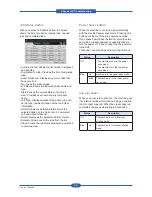
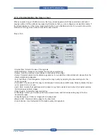
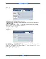
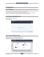
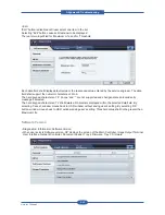
4.1.6.5 Understanding the Stored Documents screen
• Public tab : Shows the job list of delay print and store print job.
• Secured tab : Shows the job list of secure print, secure receive, and secure store print job.
• User Name : Shows the user name who registered the job.
• File Name : Shows the job name which is registered as the job information. For the computer printing, the
file name shows.
• Date : Shows the date of the job registered.
• Page : Shows the total page number of the job.
• Detail : Pops the separate message showing the basic job information with the file size, the paper size and
the paper type, as well.
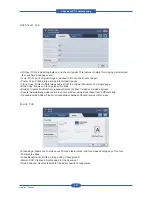
• Edit : Lets you to modify the file name.
• Delete : Deletes the selected list.
• Delete All : Deletes all the list.
• Print : Prints the selected list.
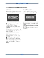
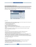
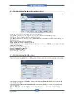
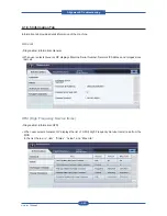
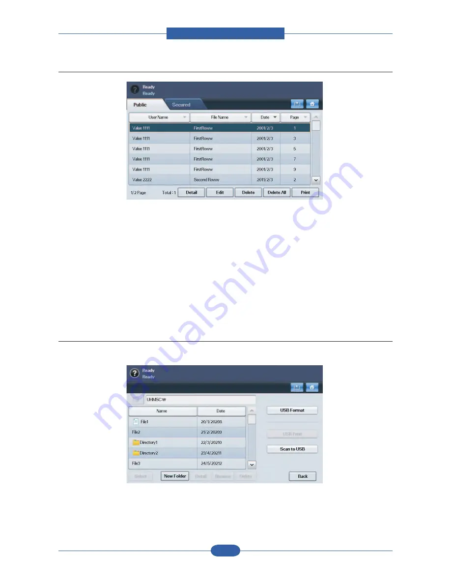
4.1.6.6 Understanding the USB screen
When USB memory is inserted into the USB memory port on your machine, USB icon shows on the display
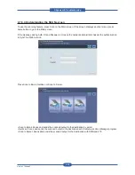
• USB Format: You can delete image files stored on an USB memory device one by one or all at once by
reformatting the device.
• USB Print: You can directly print files stored on an USB memory device. You can print TIFF, BMP, JPEG,
PDF, and PRN files.
• Scan to USB: You can specify image size, file format, or color mode for each scanning to USB job.
Summary of Contents for MFX-C4000
Page 2: ......
Page 14: ...Precautions Service Manual 1 6 ...
Page 35: ...Service Manual 2 21 Video Controller Power Distribution Product Specifications and Features ...
Page 37: ...Service Manual 2 23 Engine Controller Power Distribution Product Specifications and Features ...
Page 39: ...Service Manual 2 25 DADF Block Diagram Product Specifications and Features ...
Page 106: ...Maintenance and Disassembly Service Manual 3 44 ...
Page 216: ...Alignment Troubleshooting Service Manual 4 110 ...
Page 217: ...System Diagram Service Manual 5 1 5 System Diagram 5 1 Block Diagram 5 1 1 System ...
Page 218: ...System Diagram Service Manual 5 2 5 1 2 Video Controller ...
Page 219: ...System Diagram Service Manual 5 3 5 1 3 Engin Controller ...
Page 220: ...System Diagram Service Manual 5 4 5 1 4 OPE Unit ...
Page 221: ...System Diagram Service Manual 5 5 5 1 5 DADF ...
Page 222: ...System Diagram Service Manual 5 6 5 1 6 SCF HCF ...
Page 225: ...System Diagram Service Manual 5 9 5 2 3 OPE Unit ...
Page 226: ...System Diagram Service Manual 5 10 5 2 4 DADF ...
Page 227: ...System Diagram Service Manual 5 11 5 2 5 SCF HCF ...
Page 228: ...System Diagram Service Manual 5 12 ...
Page 237: ...Reference Information Service Manual 6 9 ...
Page 238: ...Reference Information Service Manual 6 10 ...
Page 239: ...Reference Information Service Manual 6 11 ...
Page 240: ...Reference Information Service Manual 6 12 ...
Page 279: ......


