


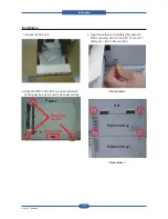


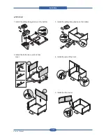


Installation
Service Manual
7-20
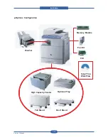
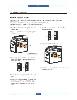
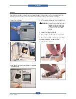
7.2.5 HCF
U
nit ( High Capacity Feeder )
HCF Unit is optional paper feeding unit of device unit
.
The HCF Unit give assistance to paper feeding capacity of
2,
100 sheets.
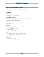
Product Spec.
1) Type of Unit : Pedestal style
2) Paper capacity : 2,100 sheets (A4 80g/
㎡
)
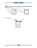
3) Paper Loading : Front Loading
4) Paper Size : A4 SEF,LETTER SEF,FOLIO SEF,LEGAL SEF (Short Edge Feeding)
5) Paper Speed : 48ppm(A4), 50ppm(LETTER)
6) Dimension : 415×540×468.5mm (W × D × H mm)
7) Weight : 25 Kg (Net, empty paper)
8) Environment
- Installation reference temperature, humidity : 15~ 25
℃
, 30 ~ 70% RH
9) Power : 24V/5V from Engine
- input power : 24V ± 10%, 3.3V ± 5%
- Current consumption
Average : Max.1.5A/24V(target), Max.0.5A/5V(target)
Max : Max. 3A
10) Noise
- HCF Printing Average Noise (Sound Level Meter) : Ave. 55dB
- HCF Printing Impulse Noise (Sound Level Meter) : Max. 65dB
11) Connection type : Drawer Connector
12) Motor Drive
- Paper feeding : BLDC Motor
- Bottom knock up plate lifting : DC geared motor
Summary of Contents for MFX-C4000
Page 2: ......
Page 14: ...Precautions Service Manual 1 6 ...
Page 35: ...Service Manual 2 21 Video Controller Power Distribution Product Specifications and Features ...
Page 37: ...Service Manual 2 23 Engine Controller Power Distribution Product Specifications and Features ...
Page 39: ...Service Manual 2 25 DADF Block Diagram Product Specifications and Features ...
Page 106: ...Maintenance and Disassembly Service Manual 3 44 ...
Page 216: ...Alignment Troubleshooting Service Manual 4 110 ...
Page 217: ...System Diagram Service Manual 5 1 5 System Diagram 5 1 Block Diagram 5 1 1 System ...
Page 218: ...System Diagram Service Manual 5 2 5 1 2 Video Controller ...
Page 219: ...System Diagram Service Manual 5 3 5 1 3 Engin Controller ...
Page 220: ...System Diagram Service Manual 5 4 5 1 4 OPE Unit ...
Page 221: ...System Diagram Service Manual 5 5 5 1 5 DADF ...
Page 222: ...System Diagram Service Manual 5 6 5 1 6 SCF HCF ...
Page 225: ...System Diagram Service Manual 5 9 5 2 3 OPE Unit ...
Page 226: ...System Diagram Service Manual 5 10 5 2 4 DADF ...
Page 227: ...System Diagram Service Manual 5 11 5 2 5 SCF HCF ...
Page 228: ...System Diagram Service Manual 5 12 ...
Page 237: ...Reference Information Service Manual 6 9 ...
Page 238: ...Reference Information Service Manual 6 10 ...
Page 239: ...Reference Information Service Manual 6 11 ...
Page 240: ...Reference Information Service Manual 6 12 ...
Page 279: ......


