


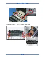


Maintenance and Disassembly
Service Manual
3-26
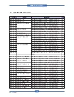
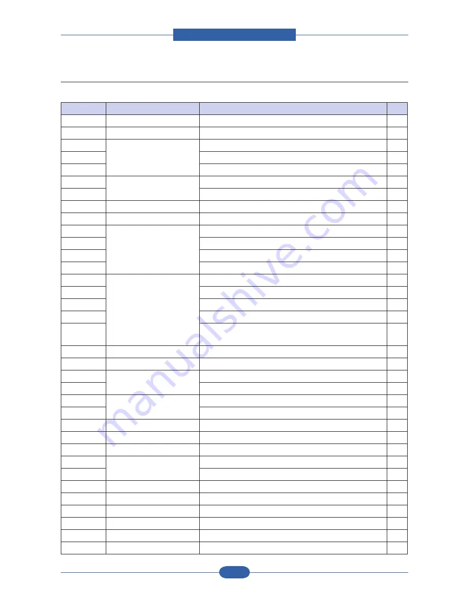
3.2.1.1 Screws used in the printer
Part_Code
Location
Description
Qty
6003-000282
ELA UNIT-LSU
SCREW-TAPTITE;BH,+,-,B,M3,L8,ZPC(BLK),SWRCH18A,-
20
6003-000282
ELA UNIT-LD_Y
SCREW-TAPTITE;BH,+,-,B,M3,L8,ZPC(BLK),SWRCH18A,-
2
6001-000130
ELA HOU-SIDE_DUPLEX
SCREW-MACHINE;BH,+,M3,L6,ZPC(WHT),SWRCH18A,-,-
2
6003-000196
SCREW-TAPTITE;PWH,+,B,M3,L10,NI PLT,SWRCH18A
24
6003-000269
SCREW-TAPTITE;BH,+,-,S,M3,L6,ZPC(WHT),SWRCH18A,-
2
6002-000440
ELA HOU-DUPLEX
SCREW-TAPPING;PWH,+,-,2,M3,L8,ZPC(BLK),SWRCH18A,-
4
6003-000196
SCREW-TAPTITE;PWH,+,B,M3,L10,NI PLT,SWRCH18A
5
6003-000264
MEA UNIT-TRAY
SCREW-TAPTITE;PWH,+,-,B,M3,L6,ZPC(WHT),SWRCH18A,-
1
6003-000196
MEA UNIT-EXIT DUPLEX
SCREW-TAPTITE;PWH,+,B,M3,L10,NI PLT,SWRCH18A
1
6003-000196
ELA UNIT-FRAME TOP
SCREW-TAPTITE;PWH,+,B,M3,L10,NI PLT,SWRCH18A
9
6003-000269
SCREW-TAPTITE;BH,+,-,S,M3,L6,ZPC(WHT),SWRCH18A,-
2
6003-001256
SCREW-TAPTITE;BH,+,B,M4,L10,NI PLT,SWRCH18A
5
6009-001492
SCREW-HEX;HWH,+,M3,L8,NI PLT,SWRCH18A,S,RF
9
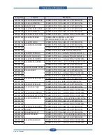
6003-000196
ELA UNIT-BASE FRAME
SCREW-TAPTITE;PWH,+,B,M3,L10,NI PLT,SWRCH18A
13
6003-000269
SCREW-TAPTITE;BH,+,-,S,M3,L6,ZPC(WHT),SWRCH18A,-
11
6003-000301
SCREW-TAPTITE;BH,+,-,S,M4,L6,ZPC(WHT),SWRCH18A,-
1
6003-001256
SCREW-TAPTITE;BH,+,B,M4,L10,NI PLT,SWRCH18A
7
6009-001396
SCREW-SPECIAL;PH,+,-,M3,L10.3,ZPC(BLK),SWRCH18A,B
TITE,-
2
6003-000282
ELA UNIT-SIZE SENSOR
SCREW-TAPTITE;BH,+,-,B,M3,L8,ZPC(BLK),SWRCH18A,-
2
6003-000266
ELA UNIT-CST SENSOR
SCREW-TAPTITE;PWH,+,-,S,M3,L6,ZPC(WHT),SWRCH18A,-
2
6003-000269
ELA UNIT-BASE PLATE R
SCREW-TAPTITE;BH,+,-,S,M3,L6,ZPC(WHT),SWRCH18A,-
13
6003-001474
SCREW-TAPTITE;BH,+,-,B,M3,L30,ZPC(WHT),SWRCH18A,-
3
6003-000196
ELA UNIT-PLATE UPPER
SCREW-TAPTITE;PWH,+,B,M3,L10,NI PLT,SWRCH18A
3
6003-000269
SCREW-TAPTITE;BH,+,-,S,M3,L6,ZPC(WHT),SWRCH18A,-
6
6003-000196
ELA HOU-MP
SCREW-TAPTITE;PWH,+,B,M3,L10,NI PLT,SWRCH18A
4
6003-000196
ELA UNIT-BASE RIGHT
SCREW-TAPTITE;PWH,+,B,M3,L10,NI PLT,SWRCH18A
6
6003-000269
MEA UNIT-RETARD
SCREW-TAPTITE;BH,+,-,S,M3,L6,ZPC(WHT),SWRCH18A,-
2
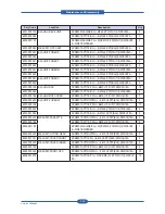
6003-000196
ELA UNIT-FRAME LOWER
SCREW-TAPTITE;PWH,+,B,M3,L10,NI PLT,SWRCH18A
85
6003-000269
SCREW-TAPTITE;BH,+,-,S,M3,L6,ZPC(WHT),SWRCH18A,-
4
6003-000196
ELA UNIT-HV ITB
SCREW-TAPTITE;PWH,+,B,M3,L10,NI PLT,SWRCH18A
4
6003-000269
ELA UNIT-WTB MOTOR
SCREW-TAPTITE;BH,+,-,S,M3,L6,ZPC(WHT),SWRCH18A,-
2
6003-000269
ELA UNIT-HOLDER OPC
SCREW-TAPTITE;BH,+,-,S,M3,L6,ZPC(WHT),SWRCH18A,-
11
6003-000196
ELA UNIT-HV TR
SCREW-TAPTITE;PWH,+,B,M3,L10,NI PLT,SWRCH18A
2
6003-000196
ELA HOU-BOTTLE BASE
SCREW-TAPTITE;PWH,+,B,M3,L10,NI PLT,SWRCH18A
13
6003-000196
ELA UNIT-HV DEVE
SCREW-TAPTITE;PWH,+,B,M3,L10,NI PLT,SWRCH18A
8
Summary of Contents for MFX-C4000
Page 2: ......
Page 14: ...Precautions Service Manual 1 6 ...
Page 35: ...Service Manual 2 21 Video Controller Power Distribution Product Specifications and Features ...
Page 37: ...Service Manual 2 23 Engine Controller Power Distribution Product Specifications and Features ...
Page 39: ...Service Manual 2 25 DADF Block Diagram Product Specifications and Features ...
Page 106: ...Maintenance and Disassembly Service Manual 3 44 ...
Page 216: ...Alignment Troubleshooting Service Manual 4 110 ...
Page 217: ...System Diagram Service Manual 5 1 5 System Diagram 5 1 Block Diagram 5 1 1 System ...
Page 218: ...System Diagram Service Manual 5 2 5 1 2 Video Controller ...
Page 219: ...System Diagram Service Manual 5 3 5 1 3 Engin Controller ...
Page 220: ...System Diagram Service Manual 5 4 5 1 4 OPE Unit ...
Page 221: ...System Diagram Service Manual 5 5 5 1 5 DADF ...
Page 222: ...System Diagram Service Manual 5 6 5 1 6 SCF HCF ...
Page 225: ...System Diagram Service Manual 5 9 5 2 3 OPE Unit ...
Page 226: ...System Diagram Service Manual 5 10 5 2 4 DADF ...
Page 227: ...System Diagram Service Manual 5 11 5 2 5 SCF HCF ...
Page 228: ...System Diagram Service Manual 5 12 ...
Page 237: ...Reference Information Service Manual 6 9 ...
Page 238: ...Reference Information Service Manual 6 10 ...
Page 239: ...Reference Information Service Manual 6 11 ...
Page 240: ...Reference Information Service Manual 6 12 ...
Page 279: ......


