MGS Installation and Operation Manual
12
1000-0085 Rev 0
Item
Description
Enclosure
Access
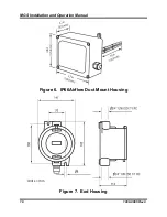
To open the standard sensor enclosure (IP41 model), turn
the cable clamp 1/2 turn counter-clockwise to loosen the
internal gland nut, depress the clip on top of the enclosure
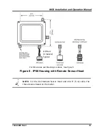
and open. Reverse to close. (Note: For the IP66 enclosure,
use the four bolts on the front cover.)
Power
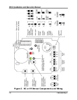
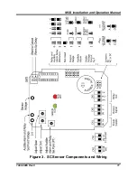
12-24V AC/DC, connect at positions 0V and +V at connector
block CN1.
•
For AC:
Jumper A is on, D is off. (See Figure 2 and
Figure 3.
•
For DC:
Jumper A is off, D is on. (Default factory setting
is DC.)
Use 2 wires, typically 18 AWG (minimum).
Output
Connect two wires to terminal block CN2 positions 0V and V
or I for voltage or current, respectively.
•
Connect 4-20mA at CN2 positions 0V and I
•
Connect voltage output at CN2 positions 0V and V
Relay Set
Point
P1 sets the trip point for the relay and audible alarm using the
0- 5V scale (measure at test points 0V and alarm test point
TP1). Default factory setting is 50% of the range.
Time
Delay
A time delay for the operation of the relay and audible alarm
can be selected using jumpers JP5 and JP6. Default factory
setting is zero.
Audible
Alarm
The audible alarm can be disabled using jumper JP2. Default
factory setting is enabled.
2.3. Machinery Rooms
There is no absolute rule in determining the number of sensors and their
locations. However, a number of simple guidelines will help to make a
decision. Sensors monitor a point as opposed to an area. If the gas leak does
not reach the sensor then no alarm will be triggered. Therefore, it is extremely
important to carefully select the sensor location. Also consider ease of access
for maintenance.
The size and nature of the site will help to decide which method is the most
appropriate to use. Locations requiring the most protection in a machinery or


