MGS Installation and Operation Manual
1000-0085 Rev 0
27
Step
Bump Testing Using Gas Ampoules
6
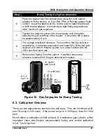
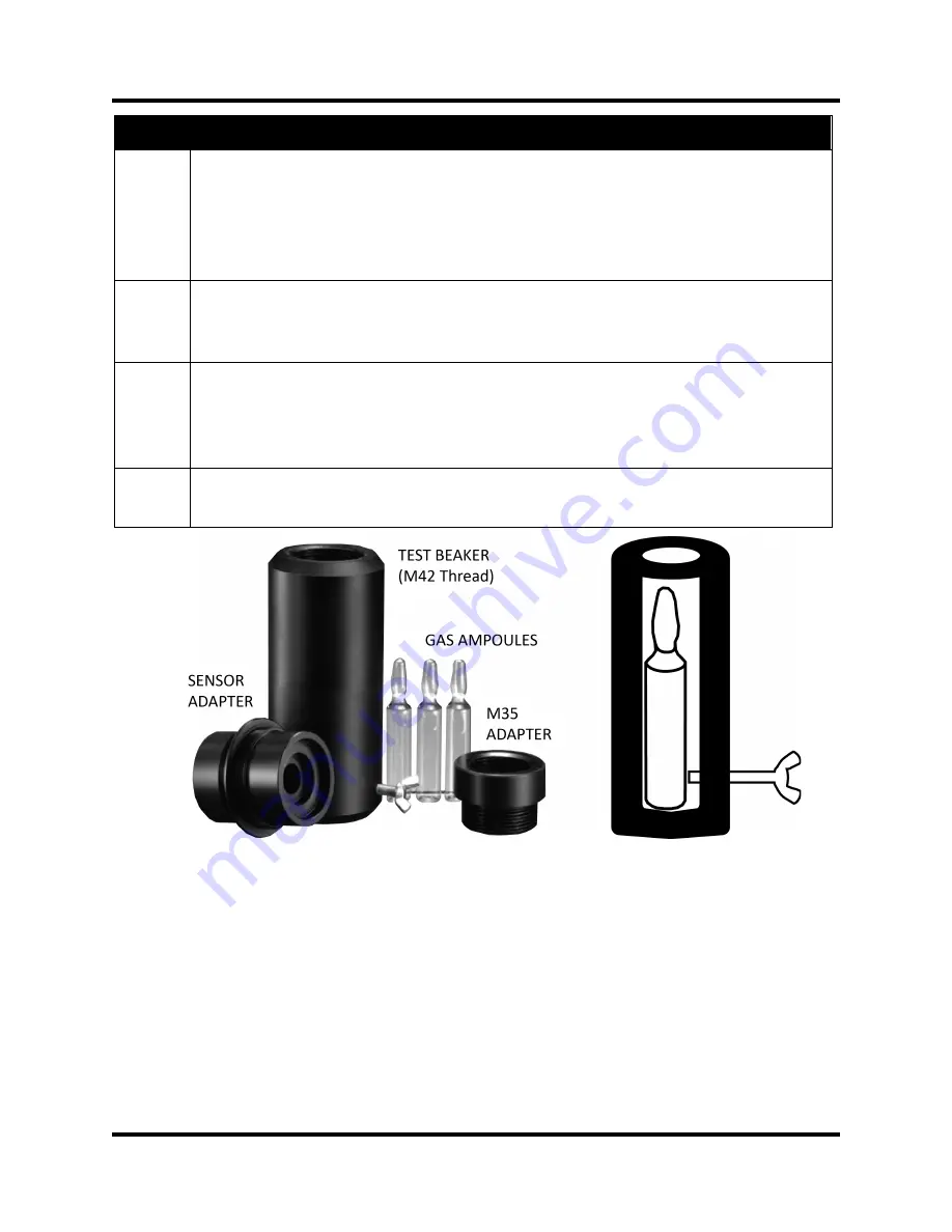
Place the beaker over the sensor head using the multi sensor
adaptor to fit the sensor, or, if an Exd, IP66 or Remote sensor head
version, screw the beaker on the remote sensor head M42 thread
or M35 thread adaptor. It should be as tight fitting as possible to
allow maximum gas exposure.
7
Tighten the wing-nut screw onto the ampoule until it shatters
allowing the gas to diffuse in the beaker. It should be left in place
for approximately 5 min.
8
The voltage output will increase. This confirms that the sensor is
responding. A response equivalent to at least 50% of the test gas
(typical) will confirm that the system is in order if tested with the
unit’s specified span gas.
9
Remove the beaker from the sensor. Carefully remove any
ampoule remains from the gas detector and beaker.
Figure 10. Gas Ampoules for Bump Testing
6.3. Calibration Overview
There are two adjustments required: zero and span. They are monitored at 0V
and VS using a 0-5V scale. If the sensor range is 0-1000 ppm, then 5V=1000
ppm.
Murco offers a calibration kit that consists of a calibration gas cylinder, a flow
regulation valve with flexible non-absorbent tubing and vented calibration
hood. Tools required:

