background image

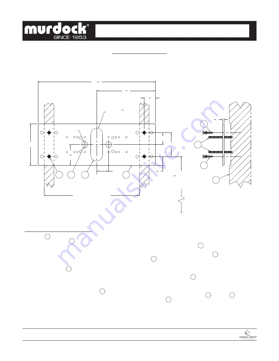
DIMENSIONAL DRAWING

Prior to roughing in, consult with local, state, and federal codes for proper mounting height.


A151-VR

Page 4 of 11

Date: 

10/28/2020

7021-020-001

MURDOCK  MFG.  • 

15125  Proctor  Avenue  •  City  of  Industry,  CA  91746  USA 

Phone  800-453-7465  or  626-333-2543  •  Fax  626-855-4860  •  www.murdockmfg.com

Member of

16" 

COMMON WALL

STUD SPACING

4"

CL

1

1
2

"

2"

2"

Ø1"

3

1
2

"

1
4

"

1

7
8

"

19

3
4

"

7"

9

7
8

"

Ø2" x 5

1
2

"

LONG OBROUND

PLATE   1   INTENDED TO BE RECESSED FLUSH WITH
SUPPORT FRAMING   2   PROVIDED BY INSTALLER.
FRAME & BLOCK OUT SUPPORT USING DIMENSIONS
SHOWN. FRAME SHOULD SUPPORT 300 LBS MINIMUM.

MOUNTING PLATE   1   IS 1/4" THICK AND INCLUDES
(18) 1/2" DIAMETER PUNCHING FOR ANCHORING
HARDWARE BY OTHERS.

STRIKE A LEVEL HORIZONTAL CHALK LINE TO
LOCATE BOTTOM MOUNTING HOLES   3  . REFERENCE
DISCHARGE HEIGHT REQUIREMENTS FOR YOUR
MODEL AND FACILITY TO DETERMINE CORRECT
HEIGHT AT FINISHED FLOOR (AFF).

AFTER POSITIONING PLATE CORRECTLY, FIX PLATE
TO WALL USING APPROPRIATE, INSTALLER PROVIDED
ANCHORING HARDWARE   4  .

MAKE UP APPROPRIATE SUPPLY   5   AND WASTE

 6   ROUGHS THROUGH MOUNTING PLATE OPENINGS.

LOCATE 5/16" THREADED STUDS MOUNTING HARDWARE 
AND THREAD STUDS   7   THRU PLATE SO THAT A
MINIMUM OF 1-1/4" OF THREAD PROJECTS BEYOND
THE FINISHED WALL MATERIAL.

PROTECT THREADED STUDS   7  , SUPPLY   5   AND 
WASTE   6   ROUGHS WHILE FINISHING WALL.

INSTALLATION INSTRUCTIONS:

A-

B-

C-

D-

E-

F-

G-

A STRAIGHT SUPPLY STOP IS RECOMMENDED.

(PLATE MAY BE MOUNTED ON FINISHED WALL, PROVIDED
FRAME SUPPORTS 300 LBS MINIMUM.)

4

4

7

2

1

6

5

3

27

1
4

FOR

 33"

DISCHARGE

HEIGHT

CONTEMPORARY WATER COOLERS


I N S TA L L AT I O N / M A I N T E N A N C E  I N S T R U C T I O N S

 DRINKING FOUNTAINS


Summary of Contents for A151-VR Series

Page 1: ...ing or improper care or abnormal use The repair or replacement of the defective materials shall constitute the sole remedy of the Buyer and the sole remedy of Murdock under this warranty Murdock shall not be liable under any circumstances for incidental consequential or direct charges caused by defects in the materials or any delay in the repair or replacement thereof This warranty is in lieu of a...

Page 2: ...nsions as required to comply with federal state and local codes A151 VR Page 2 of 11 Date 10 28 2020 7021 020 001 MURDOCK MFG 15125 Proctor Avenue City of Industry CA 91746 USA Phone 800 453 7465 or 626 333 2543 Fax 626 855 4860 www murdockmfg com Member of CONTEMPORARY WATER COOLERS I N S TA L L AT I O N M A I N T E N A N C E I N S T R U C T I O N S DRINKING FOUNTAINS GENERAL NOTES 1 ALL DIMENSIO...

Page 3: ...tor Avenue City of Industry CA 91746 USA Phone 800 453 7465 or 626 333 2543 Fax 626 855 4860 www murdockmfg com Member of SUPPLIED WALL MOUNTING PLATE 1 1 1 4 OD WASTE OUTLET 2 3 8 NCT SUPPLY INLET 3 CONTEMPORARY WATER COOLERS I N S TA L L AT I O N M A I N T E N A N C E I N S T R U C T I O N S DRINKING FOUNTAINS 2 10 3 1 21 2 3 8 271 4 295 8 28 33 2 ...

Page 4: ...CHALK LINE TO LOCATE BOTTOM MOUNTING HOLES 3 REFERENCE DISCHARGE HEIGHT REQUIREMENTS FOR YOUR MODEL AND FACILITY TO DETERMINE CORRECT HEIGHT AT FINISHED FLOOR AFF AFTER POSITIONING PLATE CORRECTLY FIX PLATE TO WALL USING APPROPRIATE INSTALLER PROVIDED ANCHORING HARDWARE 4 MAKE UP APPROPRIATE SUPPLY 5 AND WASTE 6 ROUGHS THROUGH MOUNTING PLATE OPENINGS LOCATE 5 16 THREADED STUDS MOUNTING HARDWARE AN...

Page 5: ...of Industry CA 91746 USA Phone 800 453 7465 or 626 333 2543 Fax 626 855 4860 www murdockmfg com Member of WATER TUBING CONNECTIONS CONTEMPORARY WATER COOLERS I N S TA L L AT I O N M A I N T E N A N C E I N S T R U C T I O N S DRINKING FOUNTAINS PE Tubing Mounting Plate 3 8 O D Copper Inlet ...

Page 6: ...ter supply systems in which quick acting valves are installed shall be provided with devices to absorb the hammer caused by high pressure resulting from the quick closing of the valve These pressure absorbing devices shall be approved mechanical devices Water pressure absorbing devices shall be installed as close as possible to the quick closing valve 1 Read all installation instructions carefully...

Page 7: ...TTOM FLANGES 2 ARE AGAINST FINISHED WALL SECURE TO WALL FROM THE TOP SIDES AND BOTTOM USING INSTALLER PROVIDED HARDWARE 3 C INSTALL TRIM PANEL 4 BY ENGAGING OVER JOGGLE 5 ON TOP OF FRAME 1 SEE ENGAGEMENT DETAIL D ASSEMBLY OF DRINKING FOUNTAIN THROUGH TRIM PANEL 4 INTO MOUNTING FRAME 1 HELPS SECURE TRIM PANEL 4 INTO ONTO WALL 4 5 ENGAGEMENT DETAIL NOTE TRIM PANEL FIXTURE MOUNTING POINTS 6 DIFFER TO...

Page 8: ...HE TUBE To disconnect the tube from the fitting ensure that the water line is depressurized Push collet square towards the push in fitting body and hold While holding the collet in pull on the PE tubing to remove from the push in fitting TO CUT TUBE Cut to fit length of 1 4 PE tubing and remove any burrs or sharp edges Ensure that the outside diameter is free from score marks Tube ends should be s...

Page 9: ...er Thermostat The water temperature can be adjusted using a slotted screwdriver and turning clockwise to make colder and counterclockwise to make warmer A151 VR Page 9 of 11 Date 10 28 2020 7021 020 001 MURDOCK MFG 15125 Proctor Avenue City of Industry CA 91746 USA Phone 800 453 7465 or 626 333 2543 Fax 626 855 4860 www murdockmfg com Member of 3 Periodically remove fountain top and clean out in l...

Page 10: ...t Ports on the Cartridge with the Ports in the Valve Body 1 Strainer Plug must be removed before Cartridge replacement and Strainer maintenance no need to turn the water off at the Angle Stop Some residual water will drainduring Plug removal 2 Clean Strainer as needed using clean water NOTE STRAINER SCREEN MUST BE IN PLACE FOR WATER TO FLOW Push in Fittings Strainer Plug Removal of P E Tubing from...

Page 11: ...r 9 7003 193 000 Spring Pushbutton Return 2 0116 016 000 10 32 x 3 8 Phillips Truss Head Screw 10 7003 196 199 Pushbutton Chrome 3 7000 006 000 Flat Drain Adapter Gasket 11 7003 197 199 Escutcheon Chrome 4 7000 015 000 1 1 4 OD P Trap 12 0161 062 000 6 32 x 1 2 Phillips Flat Head Screw 5 0152 010 000 10 32 x 1 Hex Flat Head Screw 13 0124 055 000 8 x 3 4 Phillips Round Head Screw 6A 7000 012 001 St...

Reviews: