background image


A172.8-UG-VR-D1-BFS

Page 6 of 17

Revised: 

02/10/21

7020-986-001

MURDOCK  MFG.  • 

15125  Proctor  Avenue  •  City  of  Industry,  CA  91746  USA 

Phone  800-453-7465  or  626-333-2543  •  Fax  626-855-4860  •  www.murdockmfg.com

Member of

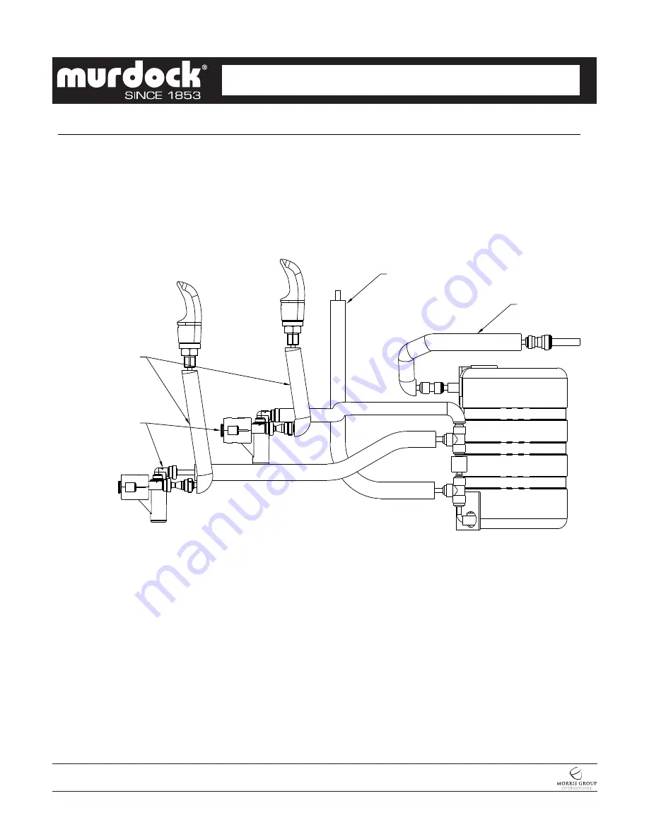
A172.8-UG-D1-BFS & A172.8-UG-VR-D1-BFS PRESSURIZED BI-LEVEL UNIT PIPING INSTALLATION

CONTEMPORARY WATER COOLERS


I N S TA L L AT I O N / M A I N T E N A N C E  I N S T R U C T I O N S

 WATER COOLERS


Cartridge Valve

Assembly

To Bottle Filler

Water Supply
Tubing

Water Supply

Tubing

Summary of Contents for A172.8-UG-D1-BFS Series

Page 1: ...placement of the defective materials shall constitute the sole remedy of the Buyer and the sole remedy of Murdock under this warranty Murdock shall not be liable under any circumstances for incidental consequential or direct charges caused by defects in the materials or any delay in the repair or replacement thereof This warranty is in lieu of all other warranties expressed or implied Product main...

Page 2: ... to increase A172 8 UG VR D1 BFS Page 2 of 17 Revised 02 10 21 7020 986 001 MURDOCK MFG 15125 Proctor Avenue City of Industry CA 91746 USA Phone 800 453 7465 or 626 333 2543 Fax 626 855 4860 www murdockmfg com Member of CONTEMPORARY WATER COOLERS I N S TA L L AT I O N M A I N T E N A N C E I N S T R U C T I O N S WATER COOLERS 1 1 4 32 O D TAILPIECE FOR P TRAP BY OTHERS 13 8 35 6 151 12 305 33 838...

Page 3: ...nents are assembled to the fixture that is not approved by Acorn Engineering 10 Fixture operates within water pressure range of 20 to 105 psig Acorn Engineering will not warranty fixtures damaged when connected to supply lines with flow pressure lower than 20 psig or higher than 105 psig A pressure regulator must be furnished by others on supply line if inlet pressure is greater than 105 psig A172...

Page 4: ...ck of the Water Coolers NOTE Hanging of refrigerated unit first is recommended since it is the heavier of the two Verify Water Coolers are level left to right AND front to back from bottom of unit CAUTION The Bubbler stream may be adversely affected if units are not square and level Bottom of units and louvers should be used as reference to verify unit is square and plumb 1 Mount Hanger Brackets t...

Page 5: ...low regulator Turning clockwise will increase flow and turning counterclockwise will decrease flow START UP 2 Air within the water cooler system or the structure supply piping will cause an irregular bubbler outlet stream until purged out by incoming water Covering the bubbler with a clean cup or similar object is recommended when first activating water cooler to prevent excessive splashing Depres...

Page 6: ... 7465 or 626 333 2543 Fax 626 855 4860 www murdockmfg com Member of A172 8 UG D1 BFS A172 8 UG VR D1 BFS PRESSURIZED BI LEVEL UNIT PIPING INSTALLATION CONTEMPORARY WATER COOLERS I N S TA L L AT I O N M A I N T E N A N C E I N S T R U C T I O N S WATER COOLERS Cartridge Valve Assembly To Bottle Filler Water Supply Tubing Water Supply Tubing ...

Page 7: ...sing a slotted screwdriver and turning clockwise to make colder and counterclockwise to make warmer c Bubbler Stream Bubbler can be rotated slightly to direct the stream backwards or forwards Adjust the stream to minimize splashing Splashing may occur from bubbler stream if the unit is not level Shim lower mounting points if necessary to level cooler 3 If water flow requires adjustment insert a sl...

Page 8: ...ndition in which the water will become frozen inside the evaporator coil This indicates a refrigeration problem or thermostat failure in which case the water cooler needs to be checked by a qualified technician 7 Water Drip Or Will Not Shut Off a Remove Pushbutton Adjust flow regulator to the highest setting using a flat head screwdriver and turning clockwise Check if water drip continues if it is...

Page 9: ...lacement and strainer maintenance no need to turn the water off at the angle stop Some residual water will drain during plug removal NOTE STRAINER SCREEN MUST BE IN PLACE FOR WATER TO FLOW 2 4 3 1 5 ITEM PART NUMBER DESCRIPTION 5 7003 830 000 UNIVERSAL MAINTANANCE TOOL 4 7003 864 000 STRAINER FILTER SCREEN 3 7003 097 001 O RING STRAINER PLUG 2 7000 060 000 FLOW REGULATOR CARTRIDGE 05 GPMG 1 7003 0...

Page 10: ...tridge 7 Reinstall strainer 4 and plug 3 using maintenance tool 5 4 Remove cartridge retaining nut 10 Remove and replace cartridge 2 When replacing cartridge be sure to align the inlet and outlet ports on the cartridge with the ports in the valve body 6 Install button assembly items 6 7 8 9 using maintenance tool 5 Insure springs are installed in button correctly NOTE STRAINER FILTER SCREEN MUST B...

Page 11: ...ing to remove from the push in fitting TO CUT TUBE Cut to fit length of 1 4 PE tubing and remove any burrs or sharp edges Ensure that the outside diameter is free from score marks Tube ends should be square 1 Firmly and fully insert the tubing end into the push in fitting up to the tube stop located approximately deep INSERTING THE TUBE COLLET COLLET O RING O RING TUBE STOP COLLET COLLET COLLET A1...

Page 12: ...RIDGE WILL REQUIRE REPLACEMENT AFTER 50 HOURS OF ACTUAL OPERATIONAL USAGE FREQUENCY OF FIXTURE OPERATION REPLACEMENT WILL DETERMINE TIME FRAME FOR CARTRIDGE IMPORTANT FLUSH 5 GALLONS OF WATER THRU THE G TURN ON WATER CHECK FOR LEAKS FILTER BEFORE ALLOWING FIXTURE USE 3 CHECK UNIT FOR PROPER OPERATION RE INSTALL BOTTOM HOUSING I IF REFRIGERATED UNIT TURN ON POWER SUPPLY AND H DISCONNECT TUBE FROM E...

Page 13: ...8 UG D1 BFS WATER COOLER PARTS BREAKDOWN DRAWING A172 8 UG VR D1 BFS Page 13 of 17 Revised 02 10 2021 7020 986 001 MURDOCK MFG 15125 Proctor Avenue City of Industry CA 91746 USA Phone 800 453 7465 or 626 333 2543 Fax 626 855 4860 www murdockmfg com Member of CONTEMPORARY WATER COOLERS I N S TA L L AT I O N M A I N T E N A N C E I N S T R U C T I O N S WATER COOLERS 19 20 9 5 1 4 2 3 13 11 14 17 16...

Page 14: ... 000 DRAIN TAIL PIECE LONG 7003 956 020 FILLER PLATE GRAY 7003 825 199 FILLER PLATE STAINLESS STEEL 11 7003 950 199 HANGER BRACKET 12 0124 050 000 8 x 3 8 LONG PHILLIPS PAN HEAD SCREW 13 1895 123 000 1 4 OD x 3 8 OD PUSH IN CONNECTION 14 7003 125 001 EVAPORATOR ASSEMBLY 15 2169 000 000 1 4 OD TUBING 16 7012 055 000 TUBE INSLULATION 17 7003 900 199 BACK PANEL 7003 302 000 FAN MOTOR 7012 062 001 FAN...

Page 15: ...STANT WATER COOLER PARTS BREAKDOWN DRAWING NOTE See page 17 for table of part numbers corresponding to drawing below Button Removal Cartridge Retaining Nut Universal Maintenance Tool from Push in Fittings Removal of P E Tubing Strainer Plug 31 CONTEMPORARY WATER COOLERS I N S TA L L AT I O N M A I N T E N A N C E I N S T R U C T I O N S WATER COOLERS 19 20 9 5 1 4 2 3 13 11 14 17 16 15 27 32 26 23...

Page 16: ...5 123 000 1 4 OD x 3 8 OD PUSH IN CONNECTION 14 7003 125 001 EVAPORATOR ASSEMBLY 15 2169 000 000 1 4 OD TUBING 16 7012 055 000 TUBE INSLULATION 7003 923 003 VANDAL RESISTANT BACK PANEL 7003 900 199 BACK PANEL 7003 302 000 FAN MOTOR 7012 062 001 FAN MOTOR 220V 19 7003 350 000 FAN BLADE 20 7003 201 000 CONDENSER 7012 801 000 COMPRESSOR 7012 030 001 COMPRESSOR 220V 7012 802 000 START RELAY 7012 031 0...

Reviews: