background image


Section 78 


00-02-0803


03-07-12

 - 

11 -


Wiring Schematic 


Summary of Contents for HelmView HV750

Page 1: ...00 02 0803 03 07 12 Section 78 HelmView ModelHV750 HVS750 Installation Manual ...

Page 2: ...ifications and designs at any time The latest version of this manual can be found at www fwmurphy com Please read the following information before installing BEFORE BEGINNING INSTALLATION OF THIS MURPHY PRODUCT Read and follow all installation instructions Please contact FW MURPHY immediately if you have any questions ...

Page 3: ...kage Contents 1 Dash Mounted Installation 1 Wiring Instructions 5 Single Engine 5 PVA and Dual Engine Gages 6 USB Wiring 7 Analog Video 8 NMEA Wiring 9 Pin Specifications for Deutsch DT04 6P Style Connections 10 Wiring Schematic 11 Specifications 12 ...

Page 4: ... THIS PAGE INTENTIONALLY LEFT BLANK ...

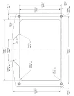
Page 5: ...ed Installation Tools needed Drill with 5 32 size bit Jig Saw Wrench or socket 6 32 Nylock nuts provided to studs Preparing the Dash Determine the location of the HelmView in the dash Use the Installation Template included at the end of the manual as a guideline to cut a hole in the dash to the specified dimensions Drill holes where indicated on the template for the mounting screws NOTE When using...

Page 6: ...h 4 Use the Nylock nuts provided to tighten unit to the dash Use the appropriate wrench or socket to tighten Torque lock nuts to 8 10 inch pounds Flush Mounting the Dash 1 Cut the dash to allow for the display without bezel Make sure enough material remains to properly secure the display within the dash Torque the 6 32 Nylock nuts to 5 inch pounds 2 Place the display behind dash and line up the fo...

Page 7: ...Section 78 00 02 0803 03 07 12 5 Wiring Instructions The following illustrations are examples of typical quick connect options for setup Wiring harnesses are sold separately Single Engine ...

Page 8: ...s NOTE Port B and C connectors are keyed differently than Port A and D connectors to ensure proper connection If both PVA gages and Video camera are going to be used an extra harness is needed P N 78000688 PVW 750 MINI Please note PVA Gages are not certified ...

Page 9: ...Section 78 00 02 0803 03 07 12 7 USB Wiring ...

Page 10: ...Section 78 00 02 0803 03 07 12 8 Analog Video NOTE If both PVA gages and video camera are going to be used an extra harness is needed P N 78000688 PVW 750 MINI ...

Page 11: ...Section 78 00 02 0803 03 07 12 9 NMEA Wiring ...

Page 12: ...efinitions CAN 3 ports according to CAN specification 2 1 port isolated according to NMEA 2000 USB 2 0 host Video input NTSC PAL Inputs 3 0 5 VDC analog inputs 1 input configurable to support measurement frequencies from 2 Hz 10kHz values from 0 100 duty cycle Output Digital capable of sinking 500mA ...

Page 13: ...Section 78 00 02 0803 03 07 12 11 Wiring Schematic ...

Page 14: ...isolated according to NMEA 2000 GPS RS 485 1 MODBUS Master port at 38 4 Kbaud Protocols J1939 NMEA 2000 Connection 5 Deutsch DT04 6P 6 pin connectors Keyboard 10 tactile buttons USB USB 2 0 host full speed Inputs 3 0 4 VDC Analog inputs 1 input configurable to support measurement frequencies from 2 Hz 10 kHz Video Input NTSC PAL Output Digital capable of sinking 500mA Environmental Certifications ...

Page 15: ...on 78 00 02 0803 03 07 12 13 Mechanical Dimensions W x H 8 37 x 6 0 in 212 5 x 152 3mm landscape Unit Depth 3 57 in 90 8mm Shipping Weight Approximately 2 5 lbs 1 13 kg Case Material Polycarbonate back case ...

Page 16: ...Section 78 00 02 0803 03 07 12 14 Intentionally Blank ...

Page 17: ......

Page 18: ......

Page 19: ......

Page 20: ......

Reviews: