background image

OPERATION

17

F–040700C

HOW TO OPERATE WITH THE MOWER HOUSING

WARNING: The deflector is a safety device. Do not re-

move the deflector. The deflector forces the dis-

charged material toward the ground. Always keep the

deflector in the down position. If the deflector is dam-

aged, replace the deflector with an original equipment

part from an authorized service center.

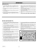
1. Start the engine.

2. Move the lift lever to a height of cut position.

IMPORTANT: In high or thick grass, cut the grass in the

highest position first and then lower the mower housing to

a lower position.

3. Move the throttle control to the SLOW position.

4. Move the blade rotation control to the ENGAGE position.

5. Push the clutch/brake pedal completely forward.

6. Move the shift lever to one of the speed settings.

NOTE: When you mow in heavy grass or mow with a

bagger, put the shift lever in the slowest speed.

7. Slowly release the clutch/brake pedal.

8. Move the throttle control to the FAST position. If you need to go

faster or slower, stop the unit and move the shift lever to another

speed setting.

9. Make sure the level of cut is still correct. After you mow a short

distance, look at the area that was cut. If the mower housing

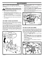
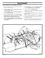
does not cut level, see the instructions on “How To Level The

Mower Housing” in the Maintenance section.

WARNING:  For better control of the unit, always

select a safe speed.

HOW TO OPERATE THE UNIT ON HILLS

WARNING: Do not ride up or down slopes that are too

steep to back straight up. Never ride the unit across

a slope. See the “Slope Guide” in the back of this

book for information on how to check slopes.

1. Before you ride up or down a hill, move the shift lever to the

slowest speed.

2. Do not stop or change speed settings on a hill. If you must stop,

quickly push the clutch/brake pedal forward and set the parking

brake.

3. To start again, make sure the shift lever is in the slowest speed.

Move the throttle control to the SLOW position. Slowly release

the pedal.

4. If you must stop or start on a hill, always have enough space

for the unit to roll when you release the brake and engage the

clutch.

5. Be very careful when you change directions on a hill. When on

a slope or in a turn on a hill, move the throttle control to the

SLOW position to help prevent an accident.

Summary of Contents for 387002x92NA

Page 1: ...rmation must be included to make sure state laws and other laws are followed PRODUCT INFORMATION Read and keep this book for future reference This book contains important information on SAFETY ASSEMBL...

Page 2: ...noted in this Limited Warranty we shall at our option repair or replace at no cost to the original purchaser any part covered by this Limited Warranty during the applicable warranty period In the even...

Page 3: ...mpletely full D Drain fuel for off season storage D Use only unleaded gasoline D Service the air cleaner regularly D Change oil regularly Use 10W 30 oil in summer D Tune up the engine regularly D Keep...

Page 4: ...e watchful care of another responsible adult 2 Be alert and turn the engine off if children enter the area 3 Before and when backing look behind and down for small children 4 Never carry children or a...

Page 5: ...on Never let another person ride with you on the unit or on any accessories A passenger will make the unit harder to control block the visibility or distract the operator and is dangerous to the opera...

Page 6: ...he mower is not correctly assembled not operated correctly or not regularly serviced the mower can be dangerous The most important rule to follow is always use good judgement and common sense Mow safe...

Page 7: ...the grass bagger always stop the engine Before each use of the grass bagger check for cracks wear or deterioration Before you use the grass bagger replace a damaged part with a replacement part appro...

Page 8: ...tments or repairs without stopping the engine Disconnect the spark plug wire F On or near roads watch out for traffic Direct discharge away from roads F When mowing avoid areas where traction is unsur...

Page 9: ...standers Away Read User Instructions Before Operating This Machine 8 WARNING Do Not Use This Machine On Slopes Greater Than 15 Degrees 9 DANGER Keep People Especially Children Away From Unit 10 DANGER...

Page 10: ...NOTE In this instruction book left and right describe the loca tion of a part with the operator on the seat NOTE Torque is measured in foot pounds metric N m This measurement describes how tight a nut...

Page 11: ...ery tilts more than 45 degrees battery acid can leak from the battery Figure 1 SIDE VIEW Battery Clamp UP Operating Position DOWN Removal Position HOW TO INSTALL THE BATTERY 1 Install the battery tray...

Page 12: ...shown Tighten the wing bolts A Figure 4 Seat Seat Adjusting Hole Seat Hinge A B HOW TO ASSEMBLE THE STEERING WHEEL Fasteners are not required to assemble the steering wheel Attach the steering wheel a...

Page 13: ...RTANT This unit is equipped with an internal combustion engine and must not be used on or near any unimproved forest covered brush covered or grass covered land unless the engine s exhaust system is e...

Page 14: ...d function is a brake HEADLIGHT SWITCH The headlight switch is the first part of the ignition switch To use the lights with the engine running turn the key to the position for the lights IGNITION SWIT...

Page 15: ...attachment 1 Before you start the engine make sure the blade rotation con trol is in the DISENGAGE position 2 Move the blade rotation control to the ENGAGE position to rotate the blade s Note If the...

Page 16: ...e the lift lever forward to lower the mower housing and back to raise the mower housing 3 When you ride on a sidewalk or road move the lift lever to the highest position and move the blade rotation co...

Page 17: ...ift lever to another speed setting 9 Make sure the level of cut is still correct After you mow a short distance look at the area that was cut If the mower housing does not cut level see the instructio...

Page 18: ...resence system that includes a sensor switch mounted in the seat These components tell the elec trical system if the operator is sitting on the seat This system will stop the engine when the operator...

Page 19: ...air pressure PSI 3 Every time you use the unit check the blade If the blade is bent or damaged immediately replace the blade Also make sure the nut for the blade is tight 4 Keep the blade s sharpened...

Page 20: ...on to keep the unit in good operat ing condition WARNING Before you make an inspection adjust ment or repair to the unit disconnect the wire to the spark plug Remove the wire from the spark plug to pr...

Page 21: ...cut correctly and can cause an accident 8 Fasten the blade with the original washers and nut Make sure the outside rim of the Belleville washer is against the blade Figure 12 WARNING Always keep the...

Page 22: ...t press tightly against the pulleys replace the mower drive belt and repeat steps 1 7 Then complete the remaining steps Correct replacement parts and assistance are available from an authorized servic...

Page 23: ...move forward Check the clearance at the rear of the pedal Figure 17 If the motion drive belt is loose the clearance will be less than 3 16 inch and the clutch will slip Adjust the clutch as follows W...

Page 24: ...n leak from the battery HOW TO CLEAN THE BATTERY 1 Remove the battery 2 Wash the battery with a solution of one gallon of water and four tablespoons of baking soda sodium bicarbonate Make sure the sol...

Page 25: ...OTE Before you replace the fuel filter or the fuel line the fuel tank must be empty If the fuel filter is dirty the engine will run rough and have less performance Remove the old filter Figure 20 Repl...

Page 26: ...r drive belt is not twisted 3 Attach the front hanger to the axle support with the hanger rod Fasten with the fasteners as shown See illustration F 4 Make sure the mower drive belt is between the stac...

Page 27: ...housing at point B will be from 0 to 1 2 0 mm to 12 mm higher than the back of the mower housing at point D SIDE VIEW Measure from the bottom of the mower housing LEVEL SURFACE B A D C Figure 22 1 Dis...

Page 28: ...igure 26 Install the motion drive belt on the top pulley of the stack pulley Make sure the V side of the belt is against the pulley 2 Push the motion drive belt through the hole in the frame for the s...

Page 29: ...lt around the right mandrel pulley 6 Pull the belt retainer away from the idler pulley Put the flat side of the mower drive belt around the idler pulley 7 Put the belt around the left mandrel pulley 8...

Page 30: ...ke sure the washer hold the hub caps in place Rear Wheel 1 Install the washers and spacer onto the axle as shown in Figure 30 2 Mount the square key in the key slot See Figure 30 3 Make sure the valve...

Page 31: ...he lever for the blade rotation control to the DISENGAGE position 4 Again clean the top of the mower housing 5 After you cut the grass clean the bottom of the mower housing STORAGE over 30 days At the...

Page 32: ...tank Clean the fuel line Replace the fuel filter PROBLEM A hot engine causes a decrease in power 1 Clean the air screen 2 Check the oil 3 Adjust the carburetor 4 Replace the fuel filter PROBLEM Exces...

Page 33: ...0 1 800 318 0201 FAX 1 801 736 8067 Colorado Idaho counties Bannock Bearlake Bingham Blaine Booneville Butte Camas Caribou Cassia Custer Franklin Fremont Gooding Jefferson Jerome Lemhi Lincoln Madison...

Page 34: ...R PARTS MODEL 387002x92NA 34 F 040700C CHASSIS HOOD 26 15 26 16 17 18 19 20 21 20 22 23 26 27 26 26 29 30 31 33 34 35 36 37 38 35 44 25 25 25 24 32 41 26 1 2 45 3 4 5 6 7 8 9 10 11 12 13 14 39 35 40 4...

Page 35: ...includes Lens 18 092344 Lens 19 009x47 Screw 20 092328E245 Fender 21 1001646E245 Console Assembly 22 26x263 Screw 23 070138 Dash Panel 24 092399 Bearing Steering 25 26x239 Screw 26 26x270 Screw 27 092...

Page 36: ...EL 387002x92NA 36 F 040700C MOTION DRIVE 24 10 11 12 13 15 16 17 18 19 20 14 55 21 23 22 25 39 40 41 45 46 49 44 1 3 5 7 6 8 9 3 4 47 52 2 9 1 3 30 3 3 51 35 48 31 32 33 26 27 14 50 29 28 34 34a 36 37...

Page 37: ...r 25 037x61 Belt Motion Drive 26 091995 Knob Shift Lever 27 091805 Z Lever Shift 28 091806 Z Yoke Shift 29 17x148 Washer 30 092694E701 Plate Belt Guide 31 06x105 Bolt Hex 32 018x32 Lockwasher 33 017x3...

Page 38: ...IR PARTS MODEL 387002x92NA 38 F 040700C STEERING 1 3 4 5 6 7 8 6 10 10 11 13 14 16 17 6 6 6 18 19 20 20 2 22 35 26 25 23 24 22 21 29 27 31 19 38 37 29 28 21 21 6 36 32 32 12 33 33 15 34 30 11 35 3 2 3...

Page 39: ...E701 Support Rear Axle 18 090038E701 Rod Tie 19 030x49 Pin Cotter 20 092527 Bearing 21 017x57 Washer 22 030x20 Pin Cotter 23 17x113 Washer 24 091828E701 Spindle Assembly Right 25 092518E701 Spindle As...

Page 40: ...REPAIR PARTS MODEL 387002x92NA 40 F 040700C MOWER HOUSING SUSPENSION 1 2 3 4 5 3 6 7 8 6 6 6 10 10 11 13 9 15 14 11 13 9 22 18 13 13 20 19 13 9 28 13 30 27 26 25 24 23 29 17 33 12 13 21 30 30 30...

Page 41: ...lange 10 092131 Nut Adjusting 11 092133E701 Bracket Adjuster Rod 12 17x124 Washer 13 0031x4 Pin Hair 14 17x122 Washer 15 090827 Z Pin Pull 17 091787E701 Lever Lower Blade Control 18 091795 Z Rod Blade...

Page 42: ...7 6 9 9 8 45 21 12 59 11 14 13 25 17 19 20 15 32 16 13 8 10 23 29 18 20 19 30 9 9 14 31 5 27 28 61 26 8 10 4 34 9 24 14 25 5 33 9 40 4 25 58 36 44 46 41 38 39 37 42 37 52 53 54 55 56 50 52 53 54 55 5...

Page 43: ...ange 26 092033E701 Crank Bell 27 009x39 Bolt Shoulder 28 092032E701 Arm Assembly Idler 29 091741E701 Plate Adjuster 30 091792E701 Cover Pulley 31 091797 Z Guide Belt 32 091813E701 Bracket Assembly Lef...

Page 44: ...REPAIR PARTS MODEL 387002x92NA 44 F 040700C ENGINE MOUNT 1 9 10 30 31 9e 9f 9a 9d 9b 9b 9c 2 3 4 5 32 12 11 13 6 7 8 11 14 21...

Page 45: ...095197 6 Screw 26x201 7 Support Dash 092331E700 8 Throttle Control 1001689 9 Engine 9a Muffler 1001720 9b Gasket Muffler 091309 9c Adapter Muffler 1001737 9d Screw Adapter 06x103 9e Bolt Muffler 009x5...

Page 46: ...K BLACK YELLOW ORANGE WHITE STARTER START SWITCH STATOR DIODE RED DC OUTPUT BLACK AC OUTPUT HEADLIGHT HARNESS SPARK PLUG ARMATURE SOLENOID ORANGE SEAT SWITCH HARNESS CLUTCH BRAKE SWITCH RED RED 15 AMP...

Page 47: ...Harness Chassis Wire 3 092377 Switch Ignition 020729 Key Ignition 091489 Nut Hex 091488 Cap Ignition 4 024273 Switch Limit 5 302031 Fuse 407078 Holder Fuse 6 094613 Solenoid 26x229 Screw Mounting 15x1...

Page 48: ...48 F 040700C...

Page 49: ...NOTES 49 F 040700C...

Page 50: ...NOTES 50 F 040700C...

Page 51: ...trol 22 Clutch 23 Drive Brake 23 Filter Fuel 25 Fuse 31 Headlight 31 Install Wheels 30 Lubrication 25 Mower Housing Clean 31 Install 26 Level 27 Remove 26 Muffler 20 Storage 31 Maintenance Chart 20 Mo...

Page 52: ...epair Parts Book LAWN SWEEPER Model No 24720 SNOW BLADE Model No 24476 SNOW THROWER Model No 24577 Made in U S A GRASS BAGGER Model No 24740 7 Bushel Capacity For 38 40 and 42 38 MULCHER KIT Model No...

Reviews: