background image

ASSEMBLY

4

F-031061C

Your Snowthrower was completely assembled at the factory,
except for the upper handle assembly.

Shipping Carton

Carefully remove complete unit from carton. Make sure parts bag
and all components have been removed before discarding
carton.

The shipping carton contains the following items:

S

Snowthrower housing, with lower handles attached.

S

Upper handle loosely attached to lower handle by the wire
harness.

S

Key, found in rear of control bar.

S

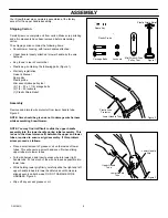
Plastic bag, containing the following parts (Figure 1):

S

Warranty registration
Owner’s Manual
Spare Key
Plastic probe
Mini wrench/drive pulley tool
(2) 1/4 – 20 x 1 1/4 carriage bolts
(2) 1/4 – 20 locknuts
(1) Plastic Strain Relief

Assembly

Remove and discard wire protector from lower handle tube.
Figure 2.

NOTE: Care should be given as not to damage wire harness
while assembling Snowthrower.

NOTE: You may find it difficult to slide the upper handle
assembly into the lower handle during initial assembly.  This
is due to the close tolerance fit between the upper and lower
tubes, required to ensure a rigid assembly.  If this problem
arises proceed as follows:

S

Place a small amount of grease or oil on the inside of lower
tubes. This will ensure a smooth and even fit when sliding
upper tubes into lower tubes.

S

Fold wire harness, and insert excess wire into lower right
handle tube. Put as much of the wire harness as possible into
lower tube.

S

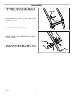
While holding lower grip firmly, carefully slide the right and left
upper handle tubes into lower handle tubes until holes are
aligned evenly on both sides. DO NOT DAMAGE WIRE
HARNESS. Figure 3.

S

Wipe off any excess grease or oil.

Plastic Probe

Spare Key

Locknuts

Mini Wrench/Drive

Pulley Tool

Plastic Strain Relief

Carriage Bolts

Figure 1

Plastic Wire

Protector

Lower Handle Tube

Figure 2

Figure 3

Upper Handle

Tube

Lower Handle

Tube

Lower Handle

Grip

Summary of Contents for 615000x30NA

Page 1: ...aring width SNOW THROWER CHASSE NEIGE De 15 po Double Isolation 12 V C A 6 5 ampères 60 hz Caution Read and Follow all Safety Rules and Instructions Before Operating This Equipment Attention Lire et respecter toutes les directives et mesures de sécurité avant d utiliser le chasse neige F 031061C LISTED SNOW MOVER 894Y File No E76832 ...

Page 2: ... purchase to an Authorized Service Center near you To locate the nearest Authorized Service Center call the Central Parts Distributor for your area shown in the list provided with your unit or check the Yellow Page listings in your local telephone directory If you return the entire unit we will repair the unit If we authorize the return of the defective part only we will either replace or repair t...

Page 3: ... from the area of operation S Avoid accidental starting Don t carry plugged in Snowthrower with finger on switch Be sure switch is off when plugging in S If Snowthrower is to be left unattended remove key and disconnect from power source S If extension cord is damaged in any way while plugged in pull extension cord from wall receptacle Replace damaged cord immediately S WARNING DON T ABUSE CORD ne...

Page 4: ...assembling Snowthrower NOTE You may find it difficult to slide the upper handle assembly into the lower handle during initial assembly This is due to the close tolerance fit between the upper and lower tubes required to ensure a rigid assembly If this problem arises proceed as follows S Place a small amount of grease or oil on the inside of lower tubes This will ensure a smooth and even fit when s...

Page 5: ...rriage bolt from outside of right handle while removing plastic probe Figure 5 S Insert carriage bolt into left handle assembly S Assemble locknuts to carriage bolts and fasten securely with mini wrench supplied S The Snowthrower although assembled at the factory should be checked over for any loose or damaged parts prior to initial use Figure 4 Plastic Probe Inside Right Handle Figure 5 Carriage ...

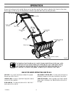
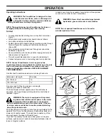
Page 6: ...an result in severe eye damage Always wear safety glasses or eye shields before starting your Snowthrower and while operating We recommend Wide Vision Safety Mask for over the spectacles or standard safety glasses available at your authorized service dealer SNOW THROWER OPERATING CONTROLS KEYLOCK Key must be inserted and rotated for operation Remove key when not in use CONTROL BAR Squeeze control ...

Page 7: ...ension cord length and size Extension cord length Wire size 25 100 Feet 16 100 150 Feet 14 Do not exceed 150 feet in extension cord length Insert key into back of control bar The Snowthrower will now operate when the control bar is squeezed The Snowthrower will stop when the control bar is released Figure 7 WARNING The motor is equipped with a protect ing device that will disconnect power to the m...

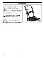
Page 8: ... full left center and full right positions Clearing Obstructed Impeller or Discharge Chute WARNING Remove key and disconnect power prior to performing any service or repairs to the Snowthrower S Use a wooden stick to clear impeller and or discharge chute S Rotate impeller by hand a few turns to make sure impeller spins freely CAUTION Failure of impeller to spin freely may result in motor damage CA...

Page 9: ...e belt tensioner as shown Figure 12 S Should it be necessary to remove drive pulley proceed as follows S Engage mini wrench drive pulley tool to drive pulley as shown Figure 13 S The mini wrench drive pulley tool will prevent the drive pulley from rotating while unscrewing pulley S Replace pulley with new pulley using the same mini wrench drive pulley tool while securing new pulley S Replace cover...

Page 10: ...10 F 031061C ...

Page 11: ...11 F 031061C Parts List Model 615000x30NA Liste de pièces Modèle 615000x30NA ...

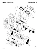
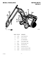
Page 12: ...MODEL 615000x30NA REPAIR PARTS 12 F 031061C 342966 ...

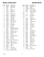
Page 13: ...acket Left Wheel 34 904977E701 Bracket Right Wheel 35 310169 Screw 36 585556 Wheel 15 37 904980 Axle 38 585564 Spacer Wheel 39 3535 Nut Push On Cap 40 578914E701 Handle Right Lower 41 578918E701 Handle Left Lower 42 905017 Bushing 43 578906E701 Handle Upper 44 579527 Protector Harness 45 903142 Harness Protector 46 577120 Set Handle Assist 46 1 Order Set 46 2 Order Set 47 578981 Set Handle Grip 47...

Page 14: ...rt No Description 60 761108 Decal Safe Operation 64 905112 Decal Start Stop 70 NOT SERVICEABLE 71 48x372 Decal MURRAY TURBO 76 905111 Decal Discharge Control 79 761068 Decal Danger Foot 84 783027 Decal Warning Cut Out 85 762049 Decal Motor Protection English 86 762050 Decal Motor Protection French ...

Page 15: ...mpagnée de votre preuve d achat auprès du Centre de maintenance agréé le plus proche de chez vous Pour localiser le centre de maintenance le plus proche contactez le Distributeur de pièces régional de votre région figurant sur la liste fournie avec votre machine ou consultez les pages jaunes de votre annuaire téléphonique local Si vous nous retournez la machine complète nous réparerons celle ci Si...

Page 16: ... interrupteur soit à l arrêt avant de brancher l appareil S Enlever la clé et débrancher l appareil s il doit être laissé sans surveillance S Débrancher la rallonge électrique immédiatement si elle est endommagée et la remplacer S AVERTISSEMENT MANIPULER LE CORDON ÉLECTRIQUE AVEC PRÉCAUTION Ne pas déplacer le chasse neige par le cordon ni le débrancher en tirant brusquement dessus Tenir le cordon ...

Page 17: ...t être difficile d assembler le manche supérieur dans le manche inférieur lors du montage initial du chasse neige Ceci est dû à la tolérance étroite entre les tubes du manche supérieur et du manche inférieur laquelle est nécessaire pour un montage rigide Dans ce cas procéder comme suit S Placer une légère quantité de graisse ou d huile à l intérieur du tube inférieur Ceci permettra aux tubes supér...

Page 18: ...ignée de droite tout en enlevant la cheville en plastique Figure 5 S Insérer le boulon à tête ronde dans le tube du manche gauche S Monter les écrous de blocage sur les boulons à tête ronde et serrer fermement avec la petite clé fournie S Bien que le chasse neige ait été assemblé en usine il doit etre examiné pour déceler toute piece desserrée ou endommagée avant la premiere utilisation Figure 4 S...

Page 19: ...isière pour travailler avec le chasse neige Nous recommandons l usage d une visière de sécurité Wide Vision s adaptant sur les lunettes ou l usage de lunettes de sécurité standard en vente chez votre concessionnaire agréé COMMANDES DU CHASSE NEIGE VERROUILLAGE À CLÉ La clé doit être insérée et tournée pour le fonctionnement Enlever la clé lorsque le chasse neige n est pas utilisé BARRE DE COMMANDE...

Page 20: ...allonge électrique et son calibre Longueur de la rallonge électrique Calibre du fil 25 100 pieds 16 100 150 pieds 14 Ne pas excéder 150 pieds de longueur de rallonge électrique Insérer la clé à l arrière de la barre de commande Le chasse neige se met en marche lorsque la barre de commande est serrée Il s arrête lorsque la barre de commande est relâchée Figure 7 AVERTISSEMENT temporairement le cour...

Page 21: ...loquera en place à droite à gauche ou au centre Nettoyage de l impulseur ou de la goulotte d éjection gelée ou obstruée AVERTISSEMENT Enlever la clé et débrancher le cor don électrique avant d effectuer tout nettoyage ou entre tien sur le chasse neige S Utiliser un morceau de bois pour dégager la turbine ou la goulotte d éjection S Faire tourner la turbine à la main pour s assurer qu elle tourne l...

Page 22: ...ation Figure 12 S Veiller à bien engager le tendeur de courroie comme le montre l illustration Figure 12 S S il est nécessaire de déposer la poulie motrice procéder comme suit S Placer la petite clé sur la poulie motrice comme le montre l illustration Figure 13 S La petite clé permet de bloquer la poulie motrice pendant son dévissage S Remplacer la poulie par une neuve en utilisant la même clé pou...

Page 23: ...23 F 031061C ...

Page 24: ...0 0491 Colorado Idaho counties Bannock Bearlake Bingham Blaine Booneville Butte Camas Caribou Cassia Custer Franklin Fremont Gooding Jefferson Jerome Lemhi Lincoln Madison Minidoka Oneida Power Teton Twin Falls Montana all counties except Flathead Lake Lincoln Mineral Missoulo Ravalli and Sanders Utah Wyoming GARDNER INC 1150 Chesapeake Ave Columbus OH 43212 614 488 7951 1 800 848 8946 Arkansas co...

Reviews: