FACILITIES & CONNECTIONS
Issue 2
Page 8 of
42
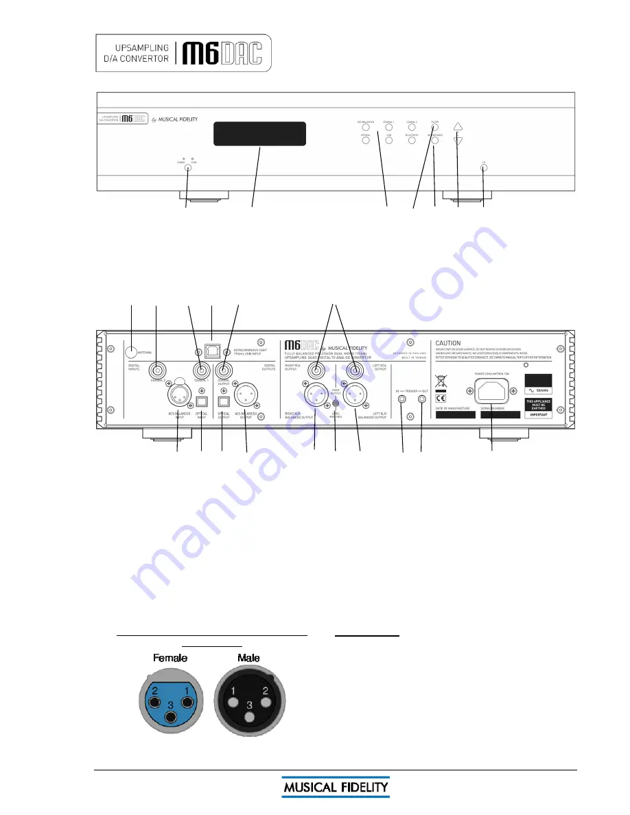
1 2 3 4 5 6 7
1
POWER
Mains ON/STBY button and LEDs
2
DISPLAY
Window
3
INPUT
selector switches
4
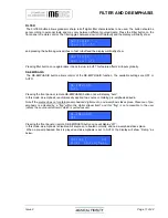
FILTER
digital filter
5
DE-EMPHASIS
off or auto
6
INPUT LEVEL
matching controls
7
IR
remote control sensor lens
8 9 10 11 12 13
14 15 16 17 18 19 20 21 22 23
8
BLUETOOTH
RP-SMA antenna socket
9
COAXIAL
digital input 2
10
COAXIAL
digital input 1
11
USB
asynchronous digital input
12
COAXIAL
digital input 1
13
RCA OUTPUTS
right and left
RCA OUTPUTS
right and left
14
AES BALANCED
digital input
14
AES BALANCED
digital input
15
OPTICAL
digital input
15
OPTICAL
digital input
16
OPTICAL
digital output
16
OPTICAL
digital output
17
AES BALANCED
digital output
17
AES BALANCED
digital output
18
XLR BALANCED OUTPUT
right
18
XLR BALANCED OUTPUT
right
19
FIXED/VOLUME MATCHED
output switch
19
FIXED/VOLUME MATCHED
output switch
20
XLR BALANCED OUTPUT
left
20
XLR BALANCED OUTPUT
left
21
TRIGGER
in 3.5mm mono jack
21
TRIGGER
in 3.5mm mono jack
22
TRIGGER
out 3.5mm mono jack
22
TRIGGER
out 3.5mm mono jack
23
MAINS
IEC socket
23
MAINS
IEC socket
Standard XLR Balanced input/output lead
Standard XLR Balanced input/output lead
connections:
(for reference only, no XLR signal leads supplied)
Pin functions:
1 Ground, 0V
2 Normal polarity ("hot" or “+”)
3 Inverted polarity ("cold" or “-“)
Note - in XLR implementation female is normally “input” and
male is “output”.


