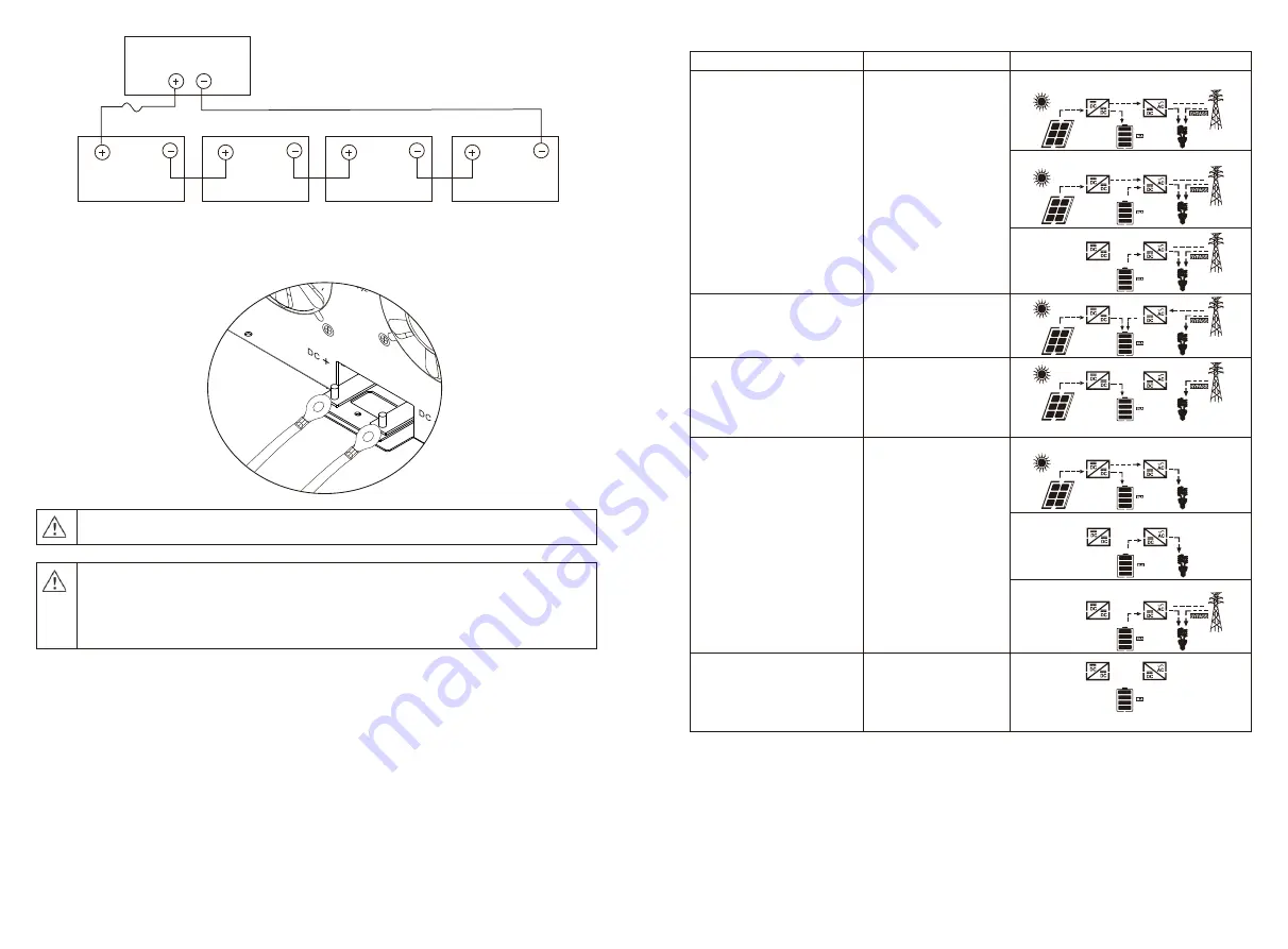
3. Insert the ring terminal of battery cable flatly into battery connector of inverter and make sure the bolts are
tightened with torque of 2-3 Nm. Make sure polarity at both the battery and the inverter/charge is correctly
connected and ring terminals are tightly screwed to the battery terminals.
6
Inverter 3KW~5KW
12V
12V
12V
12V
WARNING: Shock Hazard
Installation must be performed with care due to high battery voltage in series.
CAUTION!!
Do not place anything between the flat part of the inverter terminal and the ring terminal.
Otherwise, overheating may occur.
CAUTION!!
Do not apply anti-oxidant substance on the terminals before terminals are connected tightly.
CAUTION!!
Before making the final DC connection or closing DC breaker/disconnector, be sure positive
(+) must be connected to positive (+) and negative (-) must be connected to negative (-).
23
Off-Grid state
The inverter will provide
output power from battery
and PV power.
Inverter power loads from PV energy.
Inverter power loads from battery and PV energy.
Inverter power loads from battery only.
Stop mode
The inverter stop working if
you turn off the inverter by
the soft key or error has
occurred in the condition of
no arid.
Operating State Description
Operating State
Description
LCD display
Match load state
Note: DC power produced from
your solar array is converted by
the inverter into AC power, which
is then sent to your main electrical
panel to be used by your household
appliances. Any excess power
generated is not sold back to the
grid, but stored in battery.
PV energy is charger into the
battery or convertered by
the inverter to the AC load
PV energy power is larger than inverter power
PV energy power is smaller than inverter power
PV is off
Charge state
PV energy and grid can
charge batteries.
Bypass state
Error are caused by inside
circuit error or external
reasons such as over
temperature, output short
circuited and so on.
Summary of Contents for PV18 MPPT 3 KW
Page 1: ...420 00314 A1 3KW 5KW ...


