8
6
W A R N I N G
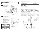
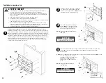
Use an assistant or mechanical lifting equipment to safely lift and position the plasma.
•
Do not tighten screws with excessive force.
Over tightening can cause damage to
mount. Tighten screws to 40 in.
•
lb
(4.5 N.M.) maximum torque.
C A U T I O N
21
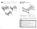
Attach wall plate assembly to
adapter bracket with another two
M8 x 15 mm screw bolt (
I
) and
two M8.2 x 1.5 x 16 mm metal
washers (
A
).
Tighten screws using 5 mm
Allen wrench (
L
).
7
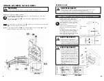
FIG. 7.2
FIG. 7.1
Be careful not to pinch fingers when
opening and closing mount fro the wall.
C A U T I O N
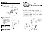
Adjust tension knob on side of mount
shown in fig. 7.1 to desired tension to
balance your screen size and weight.
The tension knob, wihout changing
the bracket tension, can be pulled
out away from the bracket and turned
independently of the knob post for
readjustment as shown fig.7.2.
Push or pull from top or bottom of
screen to adjust tilt as shown.
The tilt can be adjusted to a
maximum of 15° forward or
5° backward.
TENSION KNOB
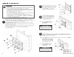
• Détecteur de montants (Un détecteur de montants
«edge to edge» est conseillé)
• Pérceuse
• Forets en acier de po
1/4
pour les montants en bois
Outils nécessaires
TABLE DES MATIÈRES
Liste de pièces . . . . . . . . . . . . . . . . . . . . . . . . . . . . . . . . . . . . . . . . . . . . . . . . . . . . . . . . . . . . . . . . . . .21
Installation de montant en bois . . . . . . . . . . . . . . . . . . . . . . . . . . . . . . . . . . . . . . . . . . . . . . . . . . . . .22
Installation du béton . . . . . . . . . . . . . . . . . . . . . . . . . . . . . . . . . . . . . . . . . . . . . . . . . . . . . . . . . . . . .23
Installation et déboulonnage de l'écran plat . . . . . . . . . . . . . . . . . . . . . . . . . . . . . . . . . . . . . . . . . . .24
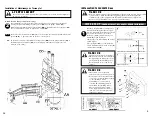
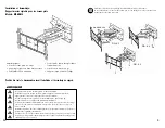
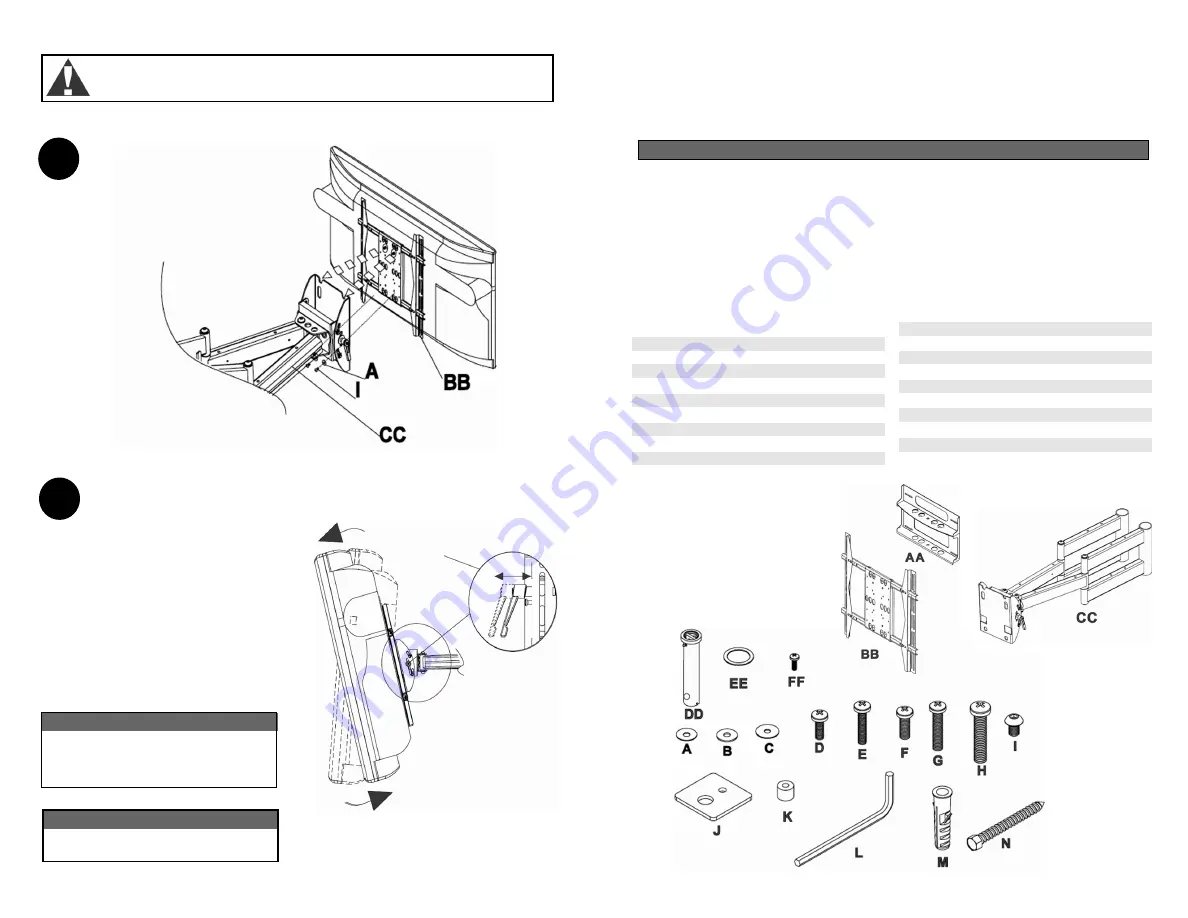
DESCRIPTION QTE
# DE PIECE
AA plaque murale
1
MV-ARM4-288161
BB corbeau d'adaptateur
1
MV-ARM4-BCP003
CC assemblage de bras porteur
1
MV-ARM4-BDC621
DD essieu portant mural de bras porteur 2
MV-ARM4-2C3Y63
EE rondelle de cuivre M48 x 39 x 1.0mm 2
0000-230151
FF vis de tête Phillips M3x 6 mm
2
0000-21A614
A rondelle métallique M8.2 x 1.5 x 16mm 4
0000-232811
B
rondelle métallique M8.2 x 2.0 x 16mm 6
0000-232A12
C
rondelle métallique M6.0 x 2.0 x 18mm 4
0000-232611
D vis à tête Phillips M5 x 16mm
4
0000-21A512
DESCRIPTION QTE
# DE PIECE
E vis à tête Phillips M5 x 30mm
4 0000-21A513
F vis à tête Phillips M6 x 16mm
4 0000-21A611
G vis à tête Phillips M6 x 30mm
4
0000-21A612
H vis à tête Phillips M8 x 45mm
4
0000-21A616
I
boulon de M8 x 15 mm
4
0000-211811
J rondelle carrée M8 x 36 mm
4
0000-232A11
K Entretoise à retenir
4 MV-ARM4-2A1661
L clé Allen 5mm
1
0000-20DF10
M ancre de mur M8 x 50 mm
6
000-2A1571
N vis en bois M8x 70mm
6
0000-21EA11
LISTE DE PIÈCES
I M P O R T A N T !
CONTINUEZ À LA PAGE APPROPRIÉ POUR VOTRE INSTALLATION.
• Forets en acier de 3/8 po pour le béton
• Niveau
• Tournevis Phillips
Avant l'installation, assurez-vous que toutes les pièces sont comprises avec votre support.
il est possible qu'il se trouve des écarts entre les parties et l'image


