7
(3) Upon completion of the wiring configuration, please check whether the wires
are securely affixed.
(4) Put the small cover back to the rear panel.
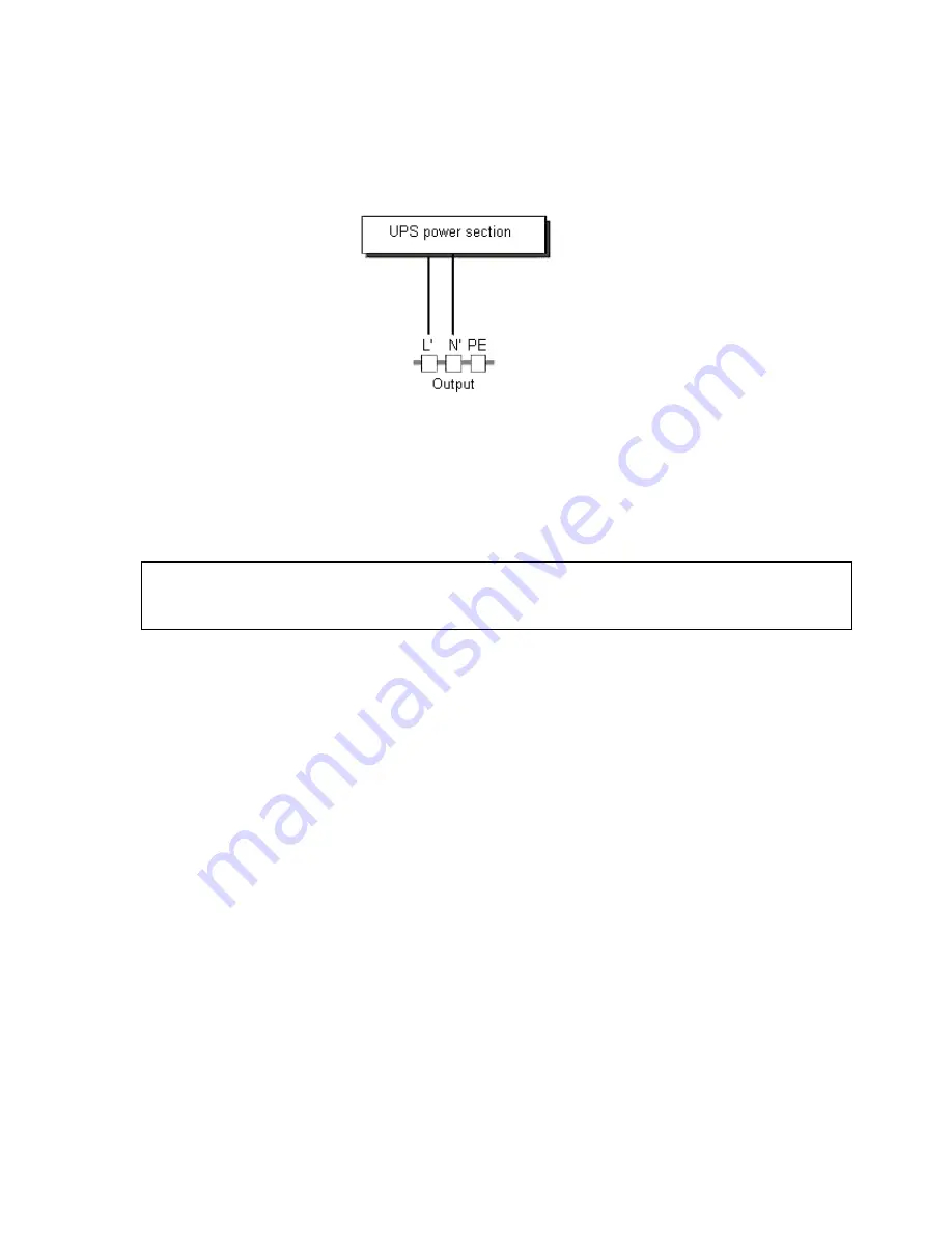
Figure 2: Connection diagram of 2KS(CE) and 3K(S)
4.2.3) Computer Connection:
Connect your computer to the outlet sockets of the UPS system following the above
diagram.
Caution!
The output sockets of the UPS system may still be electrically live even if the power
supply system has been disconnected.
4.3 Battery Charge
Fully charge the batteries of the UPS system by leaving the UPS system connected to the
mains for 1-2 hours. You may use the UPS system directly without charging it but the
stored energy time may be shorter than the nominal value specified.
4.4 Turn On
To turn on the UPS system, press the ON-Switch
“
I
“
on the front panel.
NOTE
: The INVERTER-LED lights up after 10 seconds. The BYPASS-LED then goes out
and the ventilation system switches on. The UPS system is now operating correctly.
4.5 Test Function
Test the function of the UPS system by either pressing the On-Switch
“
I
“
or disconnecting
the input of the UPS system from the power supply.
4.6 Operation Procedure of External Battery for Long Backup time Model
(
“
S
”
Model)


