background image

34

ACCESSORIES/ZUBEHÖR

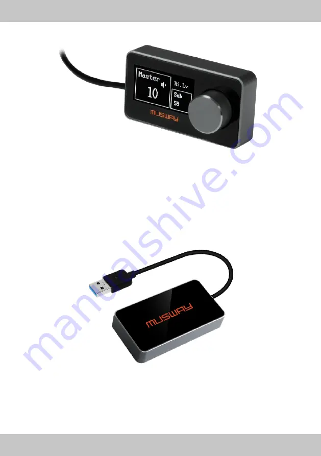
DRC1

BTS

With the DRC1 remote control, it is possible to control the overall volume and the subwoofer level on the ampli-

fier. You can also select the input signal, the subwoofer level channel pair and the DSP preset. A short press on 

the rotary knob also mutes the entire sound system. Thanks to the OLED display, the DRC1 is clearly arranged 

and only needs to be connected to the amplifier with the enclosed connection cable (5.00 m).

The BTS dongle features an audio streaming function that lets you wirelessly transfer music from your mobile 

device to the DSP amplifier. Simply connect the dongle to the DSP amplifier via USB and select the Bluetooth

®


input via software or the optional DRC1 remote control.

Mit der DRC1 Fernbedienung ist es möglich, am Verstärker die Gesamtlautstärke und den Subwoofer-Pegel zu 

regeln. Zudem kann das Eingangssignal, das Kanalpaar für den Subwooferpegel sowie das DSP-Preset aus-

gewählt werden. Durch kurzes Drücken auf den Drehknopf ist ebenfalls eine Stummschaltung des kompletten 

Soundsystems möglich. Dank der OLED-Anzeige ist die DRC1 übersichtlich zu bedienen und muss lediglich 

mit dem beiliegenden Anschlusskabel (5,00 m) an den Verstärker angeschlossen werden.

Der BTS Dongle bietet eine Audio Streaming-Funktion, mit der Sie von Ihrem Mobilgerät kabellos Musik an den 

DSP Verstärker übertragen können. Dazu müssen Sie den Dongle einfach nur über USB an den DSP Verstär-

ker anschließen und per Software oder der optionalen Fernbedienung DRC1 den Bluetooth

®

 Eingang wählen.

Summary of Contents for M6 v2

Page 1: ...M6 6 CHANNEL CLASS D AMPLIFIER WITH 8 CHANNEL DSP VERSION 1 3 V2 ...

Page 2: ...dB A Damping factor 1 kHz 2 V RMS 4 Ω 70 Input sensitivity 3 5 V 11 V RMS High level 1 5 V 4 5 V RMS Low level Input impedance 13 Ω High level 47 kΩ Low level LOAD IMPEDANCE MIN 6CH 2 Ω 3CH Bridge 1 2 3 4 5 6 4 Ω OUTPUT POWER RMS 13 8 VDC 1 THD 6CH 4 Ω 70 W x 6 6CH 2 Ω 105 W x 6 3CH Bridge 1 2 3 4 5 6 4 Ω 210 W x 3 SIGNAL OUTPUTS RCA CH7 CH8 OUT 4 V RMS Max Declaration of Conformity Audio Design G...

Page 3: ...al Stored 6 Presets GENERAL REQUIREMENTS PC connections Micro USB 1 1 2 0 3 0 Software PC requirements Microsoft Windows 32 64 bit XP Vista Windows 7 Windows 8 Windows 10 Graphic card min resolution 1024 x 768 Ambient operating temperature range 0 55 C SIZE WEIGHT Size without brackets mm 150 x 44 x 200 Net Weight kg 1 6 SCOPE OF DELIVERY 1 x M6V2 DSP Amplifier 1 x 2 5 m ISO Cable Harness with Sys...

Page 4: ...fer in this case to the chapter TROUBLE SHOOTING Otherwise risk of injury and the damage of the device consists Commit the device to an authorized retailer INTERCONNECTION AND INSTALLATION SHOULD BE ACCOMPLISHED BY SKILLED STAFF ONLY The interconnection and installation of this device demands technical aptitude and experience For your own safe ness commit the interconnection and installation to yo...

Page 5: ...S Install all the wires and cables like described on the following pages therewith these may not hinder the driver Cables and wires which are installed close by the steering wheel gear lever or the brake pedal may caught up and cause highly danger ous situations DO NOT SPLICE ELECTRICAL WIRES The electrical wires should not be bared to provide power supply to other devices Otherwise the load capac...

Page 6: ... belts gas tank or the like Ensure that the chosen location provides a sufficient air circulation for the amplifier Do not mount the device into small or sealed spaces without air circulation near by heat dispersing parts or electrical parts of the vehicle Do not mount the amplifier on top of a subwoofer box or any other vibrating parts whereby parts could loosen inside The wires and cables of pow...

Page 7: ... distance between the fuse block and the battery should be shorter than 30 cm Do not set in the fuse into the fuse block until the installation is accomplished Connect the POWER terminal ground with a suitable contact ground point on the vehicle s chas sis The ground wire must be as short as possible and must be connected to a blank metallic point at the vehicle s chassis Ensure that this ground p...

Page 8: ...e the connected speakers subwoofers with a 4 Ohm load bridge the channels as follows Channel pair 1 SPEAKER OUT1 SPEAKER OUT2 with 4 Ohms Channel pair 2 SPEAKER OUT3 SPEAKER OUT4 with 4 Ohms 1 11 2 12 3 13 4 14 5 15 6 16 7 17 8 18 9 19 10 20 HIGH LEVEL INPUT 3 HIGH LEVEL INPUT 3 HIGH LEVEL INPUT 1 HIGH LEVEL INPUT 1 HIGH LEVEL INPUT 2 HIGH LEVEL INPUT 2 HIGH LEVEL INPUT 4 HIGH LEVEL INPUT 4 SPEAKE...

Page 9: ... CH5 CH6 as well as the REM IN REM OUT connections The high level speaker inputs CH5 CH6 can be used for the separate subwoofer outputs from a car stereo head unit REM OUT is suited to turn on other devices amplifiers of the sound system such as additional amplifi ers It takes about 10 seconds to supply the signal to the REM OUT output The 200 mA output current capability can also drive an auto mo...

Page 10: ...on when an input signal is applied to the Optical input and the Bluetooth input If this LED lights up reduce the input sensitivity by using the regarding controller Input Sensitivity until the LED goes out AUX IN These stereo RCA inputs are suited for a auxiliary low level input signal from an external stereo pre amplifier source such as a game console or a media player The input sensitivity adjus...

Page 11: ... 1 1 2 0 3 0 compatible For downloading the software please visit www musway de dsp 11 12 13 14 SYSTEM CONFIGURATION Before turning on the system set the head unit output level to a lower level approximately 20 of its maximum excursion to avoid damaging the speakers during calibration WARNING In order to configure the inputs amplified speaker outputs and pre amplified power outputs EQ and time del...

Page 12: ...peaker Output 4 8 White Black 17 White 7 White Black 16 White 6 White Black 15 White 5 White Black SUBWOOFER STEREO MODE BRIDGE MODE CH1 70 W 4 Ohms 105 W 2 Ohms CH2 70 W 4 Ohms 105 W 2 Ohms CH1 CH2 210 W 4 Ohms CH3 70 W 4 Ohms 105 W 2 Ohms CH4 70 W 4 Ohms 105 W 2 Ohms CH3 CH4 210 W 4 Ohms CH5 70 W 4 Ohms 105 W 2 Ohms CH6 70 W 4 Ohms 105 W 2 Ohms CH5 CH6 210 W 4 Ohms POWER CHANNEL CONFIGURATION CH...

Page 13: ...AL APPLICATION B CD PLAYER STEREO PRE AMPLIFIER SOURCE SUBWOOFER REM OUT Rear Left WF Rear Right WF Rear Left TW Rear Right TW Front Left WF Front Right WF Front Left TW Front Right TW GROUND GROUND BATTERY FUSE HOLDER ...

Page 14: ...enclosed USB cable After you have open the DSP software you can set adjust all the audio settings on the computer The amplifier is on when the logo on the top lights up in orange After 10 seconds it becomes operative Recommended specifications CPU 1 6 GHz or higher Memory 1 GB or higher HDD 512 MB or more available space Display 1024 576 or higher OS Microsoft Windows XP Vista 7 8 or higher DSP so...

Page 15: ...automatically played louder the high level mixer detects this and mixes the radio signal without interruption 3 PARAMETRICAL 31 BAND EQUALIZER The equalizer section leaves nothing to be desired graphical real time display adjustable Q factor and separate full control of all channels including bypass function 4 EXTENSIVE FILTER SECTION Besides the separately adjustable slope for high and low pass f...

Page 16: ... connector that must be connected to the speakers which are already wired via the original sound system MPK RCA6 This two piece set is suitable for use with the DSP M6V2 amplifier in a standard installation with aftermar ket components A total of 6 RCA inputs are available for connecting the pre amplifier outputs including a remote in and out cable The amplified speaker output channels 1 to 4 lead...

Page 17: ... Recheck 3 The loudspeakers are defective Replace speakers 4 HP controller in LP BP operation is adjusted to high Turn down controller 5 For example on one or more channels are incorrectly adjusted in the DSP software Check settings Malfunction distortions on the loudspeakers Reason Remedy 1 The loudspeakers are overloaded Turn down the level Turn down the level on the head unit Switch off loudnes...

Page 18: ...Dämpfungsfaktor 1 kHz 2 V RMS 4 Ω 70 Eingangsempfindlichkeit 3 5 V 11 V RMS Hochpegel 1 5 V 4 5 V RMS Niedrigpegel Eingangsimpedanz 13 Ω Hochpegel 47 kΩ Niedrigpegel Lastimpedanz Minimum 6CH 2 Ω 3CH Gebrückt 1 2 3 4 5 6 4 Ω AUSGANGSLEISTUNG RMS 13 8 VDC 1 THD 6CH 4 Ω 70 W x 6 6CH 2 Ω 105 W x 6 3CH Gebrückt 1 2 3 4 5 6 4 Ω 210 W x 3 SIGNALAUSGÄNGE RCA Cinch Vorverstärkerausgänge CH7 CH8 4 V RMS Max...

Page 19: ...gepeichert 6 Presets Speicherplätze ALLGEMEINE ANFORDERUNGEN PC Verbindung Micro USB 1 1 2 0 3 0 Software PC Anforderungen Microsoft Windows 32 64 bit XP Vista Windows 7 Windows 8 Windows 10 Grafikkarte min Auflösung 1024 x 768 Umgebungstemperaturbereich 0 55 C GRÖSSE GEWICHT Größe ohne Montagehalter mm 150 x 44 x 200 Nettogewicht kg 1 6 LIEFERUMFANG 1 x M6 DSP Verstärker 1 x 2 5 m ISO Kabelbaum m...

Page 20: ... an einen autorisierten Händler oder den nächsten Kundendienst DIE INSTALLATION EINES PUFFERKONDENSATORS MIT AUSREICHENDER KAPAZIÄT WIRD EMP FOHLEN Hochleistungsverstärker verursachen sehr hohe Spannungsabfälle und benötigen eine sehr hohe Stromstärke bei hoher Leistung Um das Bordnetz des Fahrzeuges nicht übermäßig zu belasten wird die Installation eines Pufferkondensators auch Pufferelko Powerca...

Page 21: ...genden Seiten beschrieben damit diese beim Fahren nicht hinderlich sind Kabel die sich im Bereich des Lenkrads des Schalthebels oder im Bremspedal usw verfangen können führen zu äußerst gefährlichen Situationen ELEKTRISCHE KABEL NICHT SPLEISSEN Kabel dürfen nicht abisoliert werden um andere Geräte mit Strom zu versorgen Andernfalls wird die Strombelastbarkeit des Kabels überschritten und es besteh...

Page 22: ...ergewissern Sie sich dass der Verstärker am Montageort genügend Kühlung erhält Montieren Sie das Gerät nicht in zu kleine abgeschlossene Gehäuse ohne Luftzirkulation in die Nähe von wärmeabstrahlende Teilen oder elektronischen Steuerungen des Fahrzeuges Montieren Sie den Verstärker auf keinen Fall auf ein Bassgehäuse oder andere vibrierende Teile dadurch können sich die Bauteile im Inneren losvibr...

Page 23: ...ung sollte sich in Nähe der Batterie befinden die Kabel länge vom Pluspol der Batterie bis zur Sicherung muss aus Sicherheitsgründen unter 30 cm liegen Die Sicherung setzen Sie erst nach Abschluss aller Installationsarbeiten ein Verbinden Sie den Masseanschluss GND des Verstärkers mit einem geeigneten Massepunkt am Fahrzeugchassis Das Massekabel sollte möglichst kurz sein und an einem blanken meta...

Page 24: ...3 4 14 5 15 6 16 7 17 8 18 9 19 10 20 HOCHPEGELEINGANG 3 HOCHPEGELEINGANG 3 HOCHPEGELEINGANG 1 HOCHPEGELEINGANG 1 HOCHPEGELEINGANG 2 HOCHPEGELEINGANG 2 HOCHPEGELEINGANG 4 HOCHPEGELEINGANG 4 LAUTSPRECHERAUSGANG 4 LAUTSPRECHERAUSGANG 4 LAUTSPRECHERAUSGANG 3 LAUTSPRECHERAUSGANG 3 LAUTSPRECHERAUSGANG 2 LAUTSPRECHERAUSGANG 2 LAUTSPRECHERAUSGANG 1 LAUTSPRECHERAUSGANG 1 BATTERIE BATTERIE BATTERIE BATTERI...

Page 25: ...e Geräte des Soundsystems wie z B zusätzliche Verstärker ein zuschalten Es dauert etwa 10 Sekunden bis das Signal am REM OUT Ausgang aktiv ist Mit einer Ausgangsstromstärke von 200 mA kann auch ein automatisches Relais angesteuert werden REM IN ist geeignet um den Verstärker einzuschalten wenn ein Einschaltsignal vom Autoradio ver fügbar ist Die Spannung muss zwischen 7 5 und 15 VDC liegen 1 3 2 4...

Page 26: ...ingang und Bluetooth Eingang Wenn diese LED leuchtet verringern Sie die Eingangsempfindlichkeit indem Sie den betreffenden Regler zurückdrehen bis die LED erlischt AUX IN Diese Stereo Cinch Eingänge eignen sich für ein zusätzliches Niedrigpegel Eingangssignal von einer externen Stereo Vorverstärkerquelle wie einer Spielekonsole oder einem Media Player Die Eingangs empfindlichkeit ist von 2 bis 15 ...

Page 27: ... kompatibel Zum Herunterladen der Software besuchen Sie bitte www musway de dsp 11 12 13 14 SYSTEMKONFIGURATION Bevor Sie das System einschalten stellen Sie den Ausgangspegel des Autoradios auf ei nen niedrigeren Pegel ein ca 20 der maximalen Auslenkung um eine Beschädigung der Lautsprecher während der Konfiguration zu vermeiden ACHTUNG Um sämtliche Ein und Ausgänge den EQ und Laufzeitkorrektur fü...

Page 28: ...g 3 LS Ausgang 4 LS Ausgang 4 8 Weiß Schwarz 17 Weiß 7 Weiß Schwarz 16 Weiß 6 Weiß Schwarz 15 Weiß 5 Weiß Schwarz SUBWOOFER STEREO MODUS GEBRÜCKTER MODUS CH1 70 W 4 Ohm 105 W 2 Ohm CH2 70 W 4 Ohm 105 W 2 Ohm CH1 CH2 210 W 4 Ohm CH3 70 W 4 Ohm 105 W 2 Ohm CH4 70 W 4 Ohm 105 W 2 Ohm CH3 CH4 210 W 4 Ohm CH5 70 W 4 Ohm 105 W 2 Ohm CH6 70 W 4 Ohs 105 W 2 Ohm CH5 CH6 210 W 4 Ohm VERSTÄRKTE AUSGANGSKANÄL...

Page 29: ...SCHE ANWENDUNG B CD PLAYER VOR VERSTÄRKER STEREO QUELLE SUBWOOFER Rear Links WF Rear Rechts WF Rear Links TW Rear Rechts TW Front Links WF Front Rechts WF Front Links TW Front Rechts TW MASSE MASSE BATTERIE SICHERUNG ...

Page 30: ... Nachdem Sie die DSP Software geöffnet haben können Sie alle Einstellungen am Computer anpassen Der Verstärker ist eingeschaltet wenn das Logo auf der Oberseite orange leuchtet Nach etwas 10 Sekun den ist der Verstärker samt DSP steuerbar Empfohlene Spezifikationen CPU 1 6 GHz oder höher RAM 1 GB oder höher HDD 512 MB oder höher verfügbarer Speicherplatz Display 1024 576 oder höher OS Microsoft Wi...

Page 31: ...s jede Meldung automatisch lauter wiedergegeben wird erkennt dies der High Level Mixer und mischt das Radiosignal ohne Unterbrechung bei 3 PARAMETRISCHER 31 BAND EQUALIZER Die EQ Sektion lässt keine Wünsche offen grafische Echtzeitdarstellung einstellbarer Q Wert sowie eine separate volle Kontrolle über alle Kanäle samt Bypass Funktion 4 UMFANGREICHE FILTERSEKTION Neben der für Hoch Tiefpassfilter...

Page 32: ...rausgangskanäle 1 bis 4 enden in einem ISO Stecker der mit den bereits werkseitig verkabelten Lautsprechern verbunden werden muss MPK RCA6 Dieses zweiteilige Set eignet sich ideal für die Verwendung des DSP Verstärkers M6V2 in einer Standardinstal lation mit Nachrüstkomponenten Insgesamt stehen 6 Cinch Eingänge zum Anschluss der Vorverstärkeraus gänge inkl eines Remote In und Out Kabels zur Verfüg...

Page 33: ... Erneute Überprüfung 3 Die Lautsprecher sind defekt Lautsprecher ersetzen 4 HP Regler in Betriebsart LP BP zu hoch eingestellt Regler herunterdrehen 5 In der DSP Software ist ein oder mehrere Kanäle falsch eingestellt Einstellungen überprüfen Fehler Verzerrungen aus Lautsprecher Ursache Lösung 1 Die Lautsprecher sind überlastet Pegel niedriger einstellen Pegel am Autoradio niedriger einstellen Lou...

Page 34: ...luetooth input via software or the optional DRC1 remote control Mit der DRC1 Fernbedienung ist es möglich am Verstärker die Gesamtlautstärke und den Subwoofer Pegel zu regeln Zudem kann das Eingangssignal das Kanalpaar für den Subwooferpegel sowie das DSP Preset aus gewählt werden Durch kurzes Drücken auf den Drehknopf ist ebenfalls eine Stummschaltung des kompletten Soundsystems möglich Dank der ...

Page 35: ...reo loudspeaker system with 2 x 10⁵ Watts RMS 2 Ohms Der BTA Dongle bietet eine Audio Streaming Funktion mit der Sie von Ihrem Mobilgerät kabellos Musik an den DSP Verstärker übertragen können Dazu müssen Sie den Dongle einfach nur über USB an den DSP Verstärker anschließen und per Software oder der optionalen Fernbedienung DRC1 den Bluetooth Eingang wählen Neben der Audio Streaming Funktion biete...

Page 36: ...MUSWAY is a brand of Audio Design GmbH Am Breilingsweg 3 D 76709 Kronau Tel 49 7253 9465 0 Fax 49 7253 946510 Audio Design GmbH All Rights Reserved www musway de ...

Reviews: