Another thing worth noting is that the modulation amount of the last patch in the
modulation matrix is always attenuated by the modulation wheel. Let us say that you have
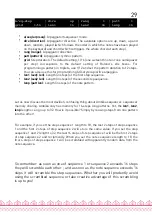
connected patch 14 from LFO 4 to the oscillators fine pitch (actually this is done by default
in the init patch!):
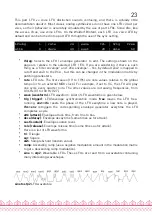
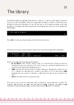
Modul. 14
| srce lfo4
| dest vibr
| amnt 16
This modulation will be applied with an amount proportional to the mod-wheel position –
by default it will not be active until you start moving the modulation wheel, and to get it at
full strength, you will have to push the modulation wheel to the max. In the modular synth
world, you would have obtained the same effect by patching the LFO at the signal input of a
VCA, the joystick at the control input of the VCA, and routed the resulting signal to the
exponential FM input of the VCO. Pheww!
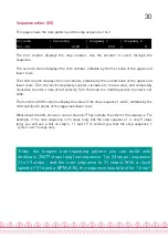
The lower page of the modulation/modifiers page allows the combination of up to 4 pairs
of modulation sources to create new modulation signals. The first knob on the bottom row
is used to select one of the 4 modulation modifiers, while the other knobs on the lower row
are respectively used to edit the two inputs of the modulation modifier (*in1* and
in2
), and
the operation (*oper*) to apply.
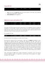
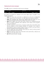
modif. 1
| in1 lfo1
| in2 lfo2
| oper prod
In the example above, the modulation source
mod 1
is defined as the product of
lfo1
and
lfo2
. The following operations are available:
•
off
no operation.
•
add
adds the values of the two modulation sources.
•
prd
computes the product of the two modulation sources.
•
attn
computes the product of a bipolar version of the first source, and the second
source.
•
max
takes the maximum of the two sources.
•
min
takes the minimum of the two sources.
•
xor
computes the bitwise XOR of the two sources.
•
greater or equal
outputs a large value if source 1 is above soure 2, 0 otherwise.
•
less or equal
outputs a large value if source 1 is below soure 2, 0 otherwise.
•
qtz
outputs the value of in1 quantized into a number of levels defined by in2. For
example, if you set a constant value (say = 4) as in2, the modulation source in1 will
be quantized into 4 discrete steps, as if it was processed through a bit-reducer! This
is useful for creating pseudo S&H effects.
•
lag
outputs the value of in1 filtered by a lowpass filter whose cutoff frequency is set
by in2. For example, if you use a constant value (say = 4) as in2, the modulation
source in1 will be strongly low-pass filtered. This is very useful for smoothing a
square or S&H lfo!
26


